09-logic Design With Asm Chart-11-07 v1d3s
This document was ed by and they confirmed that they have the permission to share it. If you are author or own the copyright of this book, please report to us by using this report form. Report 3i3n4
Overview 26281t
& View 09-logic Design With Asm Chart-11-07 as PDF for free.
More details 6y5l6z
- Words: 3,230
- Pages: 58
강의노트 09 Logic Design with ASM Charts: Based on Digital Systems Design Using VHDL, Chapter 5, by Charles H. Roth, Jr. 1
ASM Charts • Three equivalent State Machine (SM) chart State Machine Flowchart Algorithmic State Machine (ASM) chart
• Advantages of ASM charts over FSM Easier to understand the operation of a system Can be converted into several equivalent forms, and each forms lead directly to a HW realization
2
ASM Chart components • Three principal components: State box: contains • state name or code • output list (or RTL Statements)
Decision box (Condition check box): contains condition Conditional output box: contains conditional output list (or RTL Statements)
3
ASM Chart blocks • An ASM chart is constructed from ASM blocks. • Each ASM block contains exactly one state box, together with other boxes. • An ASM block has one entrance path and one or more exit paths. • Each SM block describes the system within one state. • A path through the entrance to exit is link path.
4
Equivalent ASM Chart blocks • A given ASM block can be drawn in several forms.
5
Equivalent ASM Chart blocks – cont. • Parallel form and Serial form can be equivalent. • If X1=X2=1 and X3=0, then the link paths with dashed lines are active.
6
ASM block construction rule • For every valid combination of inputs, there must be exactly one exit path. • No internal within an ASM block is allowed.
Incorrect
correct
7
ASM Chart example Could we replace this with a conditional output object? Is there any difference in operation?
8
Clock in an ASM block • The operations within a ASM block are executed with a common clock pulse while the system is in a single state T1. • At the next clock, the state will transit to either T2, T3 or T4.
An ASM chart considers the entire block as one unit. This is the major difference from a flow chart.
9
Conversion of an FSM to an ASM chart • The FSM in the example has both Mealy and Moore outputs. • The equivalent ASM chart has three blocks(for each states). • The Mealy outputs are placed in conditional output boxes.
10
Example 1: Design of a binary multiplier • A multiplier for unsigned binary numbers • Requires:
A 4-bit multiplicand A 4-bit multiplier A 4-bit full adder An 8-bit for the product (Accumulator)
Multiplicand Multiplier
1101 (13) 1011 (11) 1101 1101 100111 0000 100111 1101 10001111 (143)
Initial contents of 0 0 0 0 0 1 0 1 1 (11) (add multiplicand; M=1)
1101
after addition
011011011
after shift
001101101
(add multiplicand; M=1)
M
1101
after addition
100111101
after shift
010011110
(skip add: M=0)
after shift (add multiplicand; M=1)
001001111 1101
after addition
100011111
after shift
0 1 0 0 0 1 1 1 1 (143) 11
Example 1: Continued • This type of multiplier is called serial-parallel multiplier. (multiplier bits are processed serially, but the addition takes place in parallel) • The lower four bits in the accumulator is initially used for storing multiplicand. Initial contents of 0 0 0 0 0 1 0 1 1 (11) (add multiplicand; M=1)
1101
after addition
011011011
after shift
001101101
(add multiplicand; M=1)
Shift the contents of the to the right each time.
1101
after addition
100111101
after shift
010011110
(skip add: M=0)
after shift (add multiplicand; M=1)
001001111 1101
after addition
100011111
after shift
0 1 0 0 0 1 1 1 1 (143) 12
Example 1: Continued • ASM Chart for the control unit. • A external counter is needed for counting the number of shifts. • Inputs St (Start) M K (# of shifts=4)
• Output signals:
Load Sh (Shift) Ad (Add) Done
13
Example 1: Continued • Conversion of an ASM chart to a VHDL code is straightforward. CASE statement for each state. Condition box corresponds to an IF statement.
14
Example 2: Dice Game • Rule: (There are 2 dice to roll.) After the first roll of the dice, the player (P) wins if the sum is 7 or 11. P loses if the sum is 2, 3, or 12. Otherwise, the sum P obtained on the first roll is referred to as a point, and P must roll again. On the second or subsequent roll of the dice, P wins if the sum equals the point, and loses if the sum is 7. Otherwise, P must roll again until finally wins or loses.
15
Example 2: Dice Game - continued • Reset: to initiate a new game • Rb (Roll button): if Rb is pushed, the dice counters count at a high speed. when released, the values in the two counters are displayed, and the game proceeds.
Store sum
Flowchart 16
Example 2: Dice Game - continued • Corresponding ASM chart • Input: Rb Reset
• Conditions: D7 D711 (Sum is 7 or 11) D2312 Eq (Sum = Point)
• Outputs: Roll Sp (Sum to be stored) Win Lose 17
Example 2: Dice Game – VHDL code (1/2) entity DiceGame is port (Rb, Reset, CLK: in bit; Sum: in integer range 2 to 12; Roll, Win, Lose: out bit); end DiceGame; library BITLIB; use BITLIB.bit_pack.all; architecture DiceBehave of DiceGame is signal State, Nextstate: integer range 0 to 5; signal Point: integer range 2 to 12; signal Sp: bit; begin process(Rb, Reset, Sum, State) begin Sp <= '0'; Roll <= '0'; Win <= '0'; Lose <= '0'; case State is when 0 => if Rb = '1' then Nextstate <= 1; end if; when 1 => if Rb = '1' then Roll <= '1'; elsif Sum = 7 or Sum = 11 then Nextstate <= 2; elsif Sum = 2 or Sum = 3 or Sum =12 then Nextstate <= 3; else Sp <= '1'; Nextstate <= 4; end if; 18
Example 2: Dice Game – VHDL code (2/2) when 2 => Win <= '1'; if Reset = '1' then Nextstate <= 0; end if; when 3 => Lose <= '1'; if Reset = '1' then Nextstate <= 0; end if; when 4 => if Rb = '1' then Nextstate <= 5; end if; when 5 => if Rb = '1' then Roll <= '1'; elsif Sum = Point then Nextstate <= 2; elsif Sum = 7 then Nextstate <= 3; else Nextstate <= 4; end if; end case; end process; process(CLK) begin if rising_edge(CLK) then State <= Nextstate; if Sp = '1' then Point <= Sum; end if; end if; end process; end DiceBehave;
19
Lab 7: TB for Dice Game • Draw an ASM chart for a testbench “GameTest” with the following operations. Realize with a VHDL code. Performs simulation. the result with proper display techniques using REPORT or ASSERT, etc. 1. Initially supply the Rb signal. 2. When the DiceGame responds with a Roll signal, supply a Sum signal, which represents the sum of the two dice. 3. If no Win or Lose signal is generated by the DiceGame, repeat steps 1 and 2 to roll again. 4. When a Win or Lose signal is detected, generate a Reset signal and start again.
For the generation of Sum, use a simple method, such as reading out from a predefined array of numbers.
20
강의노트 09 Design of Complex Sequential Logics
21
Contents • Manual state machine design How to design state machines for complex synchronous sequential digital logic circuits
• “Automatic” state machine design How to convert algorithmic descriptions into HDL code that can be synthesized into working circuits The general form of the circuit that will be synthesized from an algorithmic HDL description
22
State Machine Design • Used for systematic design of synchronous sequential digital logic circuits • Modification of FSM Method FSM (Finite State Machine) method insufficient FSM method only suitable for small sequential circuits with small numbers of external inputs
• Allow more complicated checks for state transitions • Uses RTL statements within the states Within one state, all RTL statements execute concurrently
• Permits systematic conversion from algorithms to H/W • Variation of State Machine Method Algorithmic State Machine (ASM) Method • Uses a graphical notation referred to as an ASM chart 23
Algorithms • Formal definition of an “algorithm” A general step-by-step procedure for solving a problem that is CORRECT and TERMINATES.
• Properties of an algorithm Well-ordered: There is a clear order in which to do the operations. Unambiguous: Each operation is clearly understood by all intended computing agents. Effectively computable: The computing agent has ability to carry out each operation. Finite time: Each operation takes finite time and there will be a finite number of steps.
• Informal definition of an “algorithm” A computer-program-like procedure for solving the problem given.
• Algorithm description methods Old (outdated) method: flowchart Pseudocode: free-form procedural description
24
Structure of General Synchronous Sequential Circuit
25
General template for synchronous sequential circuits
26
Partitioning of Digital Circuits • Control Logic Section logic required to generate control signals for s, adders, counters, etc. “State s and state transition logics”
• Datapath Section all logic not included in the control logic section • s, adders, counters, multiplexers, etc.
typically the “word”-sized data manipulation and storage components through which the data “flows”
27
Manual State Machine Design Method (1) Pseudocode create an algorithm to describe desired circuit operation
(2) RTL Program convert the pseudocode into an RTL Program (HDL or ASM chart format)
(3) Datapath design the datapath based on the RTL Program
(4) State Diagram based on the RTL Program and the signals defined in the datapath
(5) Control Logic Design based on the state diagram
28
RTL Program • HDL Format Like a pseudocode description, except that each “step” is one state of the state machine • All operations within one state execute concurrently
All operations are RTL operations
• ASM Chart Format Uses a graphical notation that resembles a flowchart Main difference • All operations within one state execute concurrently
29
Example1: Factorial Circuits Pseudocode Step1. fact(15:0) 1; done 0; Step 2. For i=2 to n do fact fact * i; Step 3. done 1;
30
Example1: Factorial Circuits RTL Program Step1. fact(15:0) 1; done 0; count 2; Step 2. if (count ≤ n) then begin fact fact * count; count count + 1; go to Step 2; end Step 3. done 1; 31
Example1: Factorial Circuits Each “step” corresponds to a “state” in the control RTL Program logic. The RTL operations Step1. fact(15:0) 1; within a single “state” are done 0; executed concurrently. count 2; Step 2. if (count ≤ n) then begin count count + 1; fact fact * count; go to Step 2; end Step 3. done 1; 32
Datapath design rule of thumb 1. Every unique variable that is assigned a value in the RTL program can be implemented as a (PIPO, Shift , counter, etc.) 2. If there is a variable that is assigned different values at different points in the RTL program, then a multiplexer or a tri-state bus structure is necessary. 3. Accepts Control signal inputs to control the operation of the various datapath components. 4. Produce Status signal outputs to Control logic. 5. A few optimizations may be possible by combining s, adders or other components.
33
Rule of thumb applied in our example 1. Every unique variable that is assigned a value in the RTL program can be implemented as a (PIPO, Shift , counter, etc.) • count, fact in our example • fact can be implemented with a simple ; count with a counter
2. If there is a variable that is assigned different values at different points in the RTL program, then a multiplexer or a tristate bus structure is necessary. • fact is either initialized or have the value fact*count
3. Accepts Control signal inputs to control the operation of the various datapath components. 4. Produce Status signal outputs to Control logic. 5. A few optimizations may be possible by combining s, adders or other components.
34
Example1: Factorial Circuits Datapath Control Signals
Status Signals
35
Control Logic Design Methods • One-FF-per-state method also referred to as “one-hot encoded” or “delay element” method uses one FF for each state of the state machine
• Binary encoded state method uses encoded states • number of FFs used = integer_part (log (number_of_states))
results in the most compact implementation
• Gray encoded state method • Sequence-counter method for use with cyclical state transition patterns • e.g., a U with equal numbers of states for each instruction
outputs of the “counter” are the control logic “states”
36
One-FF-Per-State Method • Uses one-to-one transformations from state diagram to digital logic components Also applicable to ASM charts
• Transformations state in state diagram • transforms to a D flip-flop
transition from one state to another in state diagram • transforms to a path from the Q or Q‟ output of one state flip-flop to the D input another D flip-flop
labeled transition in state diagram • AND gate with the labeled condition • labeled (conditional) signal activation also leads to AND gate
Several transitions into a single state • OR gate with one input for each transition
37
One-FF-Per-State Method Example
38
Conversion from ASM chart to logic
39
Example1: Factorial Circuits – Status Signals State diagram Control Signals
• For the Control logic design, a state diagram is helpful. • The state diagram here is restrictive diagram than formal Finite State Machine (FSM).
40
Example1: Factorial Circuits – Control logic
41
Example1: Factorial Circuits – Control logic
42
Example2: Four-Phase Handshake Transmitter Circuit • Used to communicate between two circuits in different clock domains (i.e., clocked by different clock signals) In large or high-performance circuits, different circuits (or subcircuits) will use different clock inputs because of clock synchronization difficulties or simply because they are independent circuits. Communication of data packets between such circuits requires a handshaking protocol
43
Handshake protocols
44
Example2: Four-Phase Handshake Transmitter Circuit: Pseudocode 1. req 0; wait until ready = 1; -- data ready 2. DATA data_to_be_sent; 3. req 1; -- assert request wait until ack = 1; 4. req 0; wait until ack = 0; 5. go to Step 1;
45
Example2: Four-Phase Handshake Transmitter Circuit:
ASM Chart
46
Example2:
ASM Chart to Datapath
• req is output. • data_to_be_sent, ready and ack are inputs. • There is only one variable in the pseudocode: DATA
47
Example2: Four-Phase Handshake Transmitter Circuit:
ASM Chart to Logic
48
Overall Manual State Machine Design Approach • Write down a pseudocode solution test it out using a short computer program
• Convert the pseudocode to an RTL program try to “optimize” ASM chart, so it uses a small number of states can use HDL format or ASM chart format
• Derive the datapath from the RTL program figure out the datapath components and signals needed
• Form a state diagram with states and control signal activations • Derive the control logic design one-hot or PLD-based approach
49
Contents • Manual state machine design How to design state machines for complex synchronous sequential digital logic circuits
• “Automatic” state machine design How to convert algorithmic descriptions into HDL code that can be synthesized into working circuits The general form of the circuit that will be synthesized from an algorithmic HDL description
50
Automatic State Machine Design 1. Describe the desired circuit using pseudocode. Many engineers adopt C itself as the language for pseudocode in order to simulate and to the algorithm.
2. Convert the pseudocode into an HDL program. Conversion from an ASM chart into a synthesizable VHDL code can be done through special EDA tools. Inherently concurrent nature of hardware must be kept in mind when writing an HDL code.
3. Use a synthesis tool to convert the HDL code into a working hardware circuit. Implement for the target hardware architecture. 51
Recommended Pseudocode Format for HDL code conversion (0) initialize variables; while (true) do (1) first step of algorithm; (2) second step of algorithm; ... (k) for (i = 0; i < max; i++) … ... (m) call to function FUNCTION; … (n) n‟th step of algorithm endwhile 52
Recommended Pseudocode Format for HDL code conversion • Initialization is followed by an infinite while loop. • Operation in while loop can include assignment to variables arithmetic/logic operations conditional actions calls to subroutines/functions for/while loops.
• Loops can be either with operations that can be performed concurrently or as a series of sequential steps with delay between the steps.
53
Pseudocode to HDL conversion
54
Corresponding Synthesizable VHDL Code alg: process (reset_n, clk) is begin if (reset_n = „0‟) then state <= (others => „0‟); (other initialization operations); elsif rising_edge(clk) then state <= state + 1; -- auto-increment state case (state) is when “0000” => -- first step of algorithm when “0001” => … -- second step of algorithm when “0010” => ret_state <= “0011”; state <= FUNCTION_1; when “0011” => … when FUNCTION_1 => … -- 1st step of function … when FUNCTION_1+k => state <= ret_state; -- return from function when others => report “Unknown state!”; end case; end if; -- of elsif rising_edge(clk) end process alg; 55
Example: Two-Phase Handshake Transmitter Circuit
• Used to communicate between two circuits in different clock domains (i.e., clocked by different clock signals) In large or high-performance circuits, different circuits (or subcircuits) will use different clock inputs because of clock synchronization difficulties or simply because they are independent circuits Communication of data packets between such circuits requires a handshaking protocol
• Solution implemented using the automatic synthesis-based method instead of the manual state machine design method used in Example 5.2
56
Pseudocode 1. req 0; while (TRUE) do 2. wait until (ready = 1); -- data ready 3. data data_to_be_sent; 4. req not req; -- invert req value 5. wait until (ack = req); end while;
57
Synthesizable VHDL Code • proc1: process (reset_n, clk) is begin if (reset_n = „0‟) then req <= „0‟; state <= “00”; -- state should be a 2-bit unsigned signal elsif rising_edge(clk) then -- on posedge clk state <= state + 1; -- auto-increment current state case (state) is when “00” => if (ready = „0‟) then state <= “00”; -- repeat until ready end if; when “01” => data <= data_in; -- assume data_in is data to be sent when “10” => req <= not req; -- send request signal when others => if (ack /= req) then -- case “11” state <= “10”; -- stay in this state until (ack = req) end if; end case; end if; -- of elsif rising_edge(clk) end process proc1;
58
Related Documents 3h463d
09-logic Design With Asm Chart-11-07 v1d3s
August 2021 0
Asm Mlc 1h4e6g
December 2019 48
Asm Chart 15y1m
April 2022 0
Asm Aritmetica 46136s
August 2021 0
Asm Md 6q5g23
October 2021 0
Oracle Asm 612l1q
December 2019 77More Documents from "Sandeep Chaudhary" 4p7071
09-logic Design With Asm Chart-11-07 v1d3s
August 2021 0
Cost ing - Mcqs 5m274p
October 2019 64
Aircel Policy Manual 1w4z1f
December 2019 23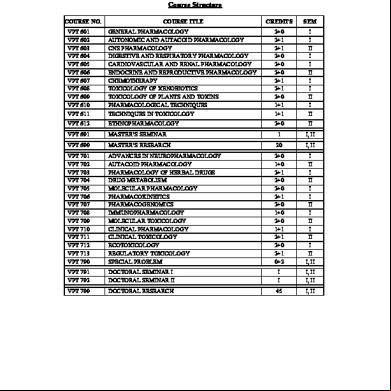
Veterinary-pharmacology-toxicology.pdf 946w
November 2019 30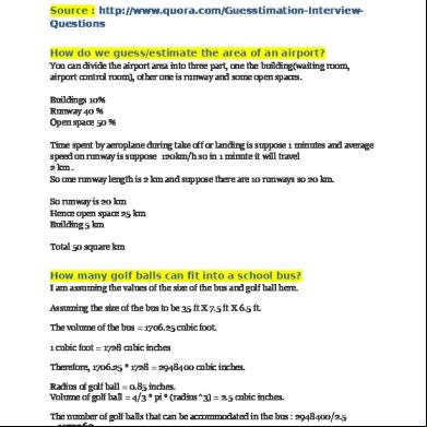
Guess Estimate Questions 5g4t6b
December 2019 132