Actair a4m5s
This document was ed by and they confirmed that they have the permission to share it. If you are author or own the copyright of this book, please report to us by using this report form. Report 3i3n4
Overview 26281t
& View Actair as PDF for free.
More details 6y5l6z
- Words: 3,113
- Pages: 16
Technical leaflet 8515.1/3--10
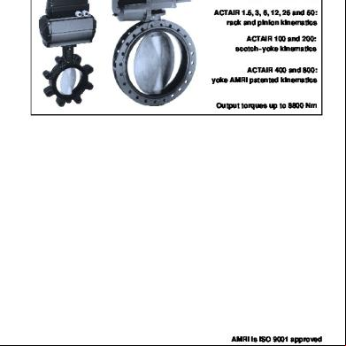
ACTAIR 1.5 to 800 pneumatic actuators Double acting pneumatic actuators ACTAIR 1.5, 3, 6, 12, 25 and 50: rack and pinion kinematics ACTAIR 100 and 200: scotch-- yoke kinematics ACTAIR 400 and 800: yoke AMRI patented kinematics
Output torques up to 8800 Nm
AMRI is ISO 9001 approved
ACTAIR 1.5 to 800 pneumatic actuators General features Designed for the automation of ¼ turn valves (butterfly valves, ball valves), the ACTAIR series of double acting pneumatic actuators and their AMTRONIC box are involved in all functions of control and supervision encountered in all modern processes, and more particularly in communication by fieldbus. 3 kinematics are used for the actuators operation: -- rack and pinion kinematics for ACTAIR 1.5, ACTAIR 3, ACTAIR 6, ACTAIR 12, ACTAIR 25 and ACTAIR 50, -- scotch--yoke kinematics for ACTAIR 100 and ACTAIR 200, -- yoke AMRI patented kinematics for ACTAIR 400 and ACTAIR 800. Mounting plate according to ISO 5211 standard. Equipped with an interchangeable insert, they can be easily fitted on different valve shaft (square end, flat end, key). The ACTAIR series actuators are equipped, in standard version, with a visual pointer and adjustable mechanical travel stops: -- on the closed or open positions for ACTAIR 1.5 to 200, -- on the closed and open positions for ACTAIR 400 and 800. The actuator is mounted directly or by means of an adaptator on ¼ turn valve plate.
Protection: They are hose and fine dust proof and are protected against accidental immersion effects (protection degree: IP 67).
External coating: ACTAIR 1.5 to 200: Housing with hard anodization 50 ←m thickness and cylinder head with polyurethane paint (colour blue RAL 5002, 80 ←m thickness). ACTAIR 400 and 800: Polyurethane paint (colour dark grey RAL 7016, 80 ←m thickness).
Working temperature range: From –20° to +80° C: standard, From –20° to –40° C and from +80° to +120° C: consult us. This double acting actuator range is completed by the DYNACTAIR series spring return actuator range which is based on the double acting actuators. Please consult the technical leaflet DYNACTAIR 1.5 to 800 no. 8511.1.
Production range Maximum allowable dimensions for the shaft ACTAIR
ISO 5211 Mounting plate*
Height Driving Type by square 1.5 F04 24 11 3 24 11 F04* (45° ) – F05 6 F05 – F07 30 16 12 F05 – F07 32 19 25 F07 – F10 40 22 50 F10 – F12 45 27 100 F10 – F12 55 36 200 F14 65 50 400 F16 80 60 800 F16 – F25 95 70 * Direct adaptation onto identical mounting plate. Adaptation by intermediate flange onto different plate (different size or shape).
2
Driving by flat 11 11 14 17 22 27 36 46 55 75
Driving by key 12 12 14 18 22 28 42 50 72 80
ACTAIR 1.5 to 800 pneumatic actuators Output torques (Nm) relating to control fluid pressure The output torque of the actuator depends on the pressure of the control fluid. The table below shows different output torques as a function of control fluid pressure.
ACTAIR Type
Maximum allowable output torque (Nm)
Control fluid pressure in bar 3
4
9 25 48 89 178 357
12 33 64 115 237 475
5
6
8
18 50 96 155 350 580
20 55 105 170 385 640
Rack and pinion kinematics 1.5 3 6 12 25 50
20 55 105 170 385 640
15 40 80 140 290 520
Scotch--yoke kinematics 100 200
1320 2640
0° 600 1200
45° 360 720
90° 600 1200
0° 800 1600
45° 480 960
90° 800 1600
0° 1000 2000
45° 600 1200
90° 1000 2000
0° 1200 2400
45° 720 1440
90° 1200 2400
0° 1320 2640
45° 792 1584
90° 1320 2640
Yoke AMRI patented kinematics 400 800
4400 8800
0° 30° 60° 90° 0° 30° 60° 90° 0° 30° 60° 90° 0° 30° 60° 90° 0° 30° 60° 90° 2700 2970 2700 1350 3200 3520 3200 1600 4000 4400 4000 2000 4400 4840 4400 2200 4400 4840 4400 2200 5160 5676 5160 2580 6800 7480 6800 3400 8600 9460 8600 4300 8800 9680 8800 4400 8800 9680 8800 4400
Control fluid supply Air or any neutral gas, filtered, dry or lubricated at pressure of 3 to 8 bar.
Operation time The table below defines the minimum operation times under control air pressure 5 bar and the operation rates per minute of the ACTAIR on/off function.
ACTAIR ACTAIR Type + AMTRONIC 1.5 3 6 12 25 50 100 200 400 800
1 second 1 second 2 seconds 3 seconds 4 seconds 6 seconds 9 seconds 15 seconds 30 seconds
Mini operation time On/off function ACTAIR with distributor ISO--1 or NAMUR onto the housing
ACTAIR direct connexion
Operation rates per minute
0,5 second 0,5 second 0,5 second 1 second 1,5 seconds 2 seconds 2,5 seconds 3,5 seconds 12 seconds 25 seconds
60 maxi 60 maxi 60 maxi 30 maxi 20 maxi 15 maxi 10 maxi 7 maxi 4 maxi 2 maxi
8 seconds 15 seconds
Adjust construction on request for: -- other operation times, -- high operation rates. Consult us.
Capacity Capacity in cm3
ACTAIR Type
for opening
for closing
1.5 3 6 12 25 50 100 200 400 800
72 240 570 1180 2400 4700 5280 9800 15960 35300
100 305 660 1265 2508 4680 4380 8500 15720 35300
3
ACTAIR 1.5 to 800 pneumatic actuators Operation In the standard version, ACTAIR actuators are designed to ensure clockwise valve closure. On request, anticlockwise arrangement is available.
ACTAIR 1.5 to 50: Rack and pinion kinematics The rack and pinion kinematics develop a constant output torque. The movement of the rack/pistons secured by the pressure causes a ¼ turn clockwise rotation of the pinion integral with the valve shaft. Curve of the rack and pinion kinematics Constant output torque
Clockwise closure version – adjustable mechanical travel stop at the closed position Opening operation Actuator/Valve closed Actuator/Valve open
Closure operation Actuator/Valve open Actuator/Valve closed
Clockwise closure version – adjustable mechanical travel stop at the open position Opening operation Actuator/Valve closed Actuator/Valve open
4
Closure operation Actuator/Valve open Actuator/Valve closed
ACTAIR 1.5 to 800 pneumatic actuators ACTAIR 100 and 200: Scotch--yoke kinematics The scotch--yoke kinematics develop a variable output torque very well suited to the operation of ¼ turn valves. The movement transmission is achieved by means of the piston system ➲, rollers ➳, scotch--yoke ➴ and shaft ➵. The movement of the pistons ➲ secured by the pressure causes the sliding of the rollers ➳ in the grooves of the yoke ➴. The yoke ➴ allows the rotation of the shaft ➵ integral with the valve shaft. Curve of the Scotch yoke kinematics Output torque for F constant C = F x D
Clockwise closure version – adjustable mechanical travel stop at the closed position Opening operation Actuator/Valve closed Actuator/Valve open
Closure operation Actuator/Valve open Actuator/Valve closed
Clockwise closure version – adjustable mechanical travel stop at the open position Opening operation Actuator/Valve closed Actuator/Valve open
Closure operation Actuator/Valve open Actuator/Valve closed
5
ACTAIR 1.5 to 800 pneumatic actuators ACTAIR 400 and 800: Yoke AMRI patented kinematics The yoke AMRI patented kinematics develop a variable output torque very well suited to the operation of ¼ turn valves with hydrodynamic torque. The movement transmission is achieved by means of the piston system ➲,the slide operating nut ➳, the rolling pad ➴ and the yoke ➵. The movement of the piston ➲ secured by the pressure in the actuator cylinder causes the linear travel of the operating nut ➳. This movement drives the sliding of the pads ➴ in the 2 slides of the operating nut ➳ and allows the rotation of the yoke ➵ integral with the valve shaft. Curve of the yoke AMRI patented kinematics Output torque for F constant C = F x D
ACTAIR 400 Opening operation Actuator/Valve closed Actuator/Valve open
Closure operation Actuator/Valve open Actuator/Valve closed
ACTAIR 800 Opening operation Actuator/Valve closed
Actuator/Valve open
Closure operation Actuator/Valve open
6
Actuator/Valve closed
ACTAIR 1.5 to 800 pneumatic actuators ACTAIR 1.5 to 50 Construction Pneumatic connection (¼’’ Gas). Section A--A
Item Designation 103 Housing 163 Cylinder head 300.1 Upper bearing 300.2 Lower bearing 314 Thrust washer 410 Cylinder head gasket 412.1 O--ring 412.2 O--ring 412.3 Piston O--ring 412.4 O--ring 412.6 O--ring 486 Ball 554 Washer 55--2 Friction washer 593 Piston bearing 595 Piston 629 Pointer 81--68 Piston guide 877 Pinion 903 Plug 904 Socket screw 909 Adjusting screw 914.1 Hexagon socket head screw 916 Plug 920 Hexagonal nut 932 Spring retaining ring Parts included in the spare parts kit
Section B--B
Materials Light alloy with 50 ←m hard anodization Light alloy coated with polyurethane paint 80 ←m Acetal Acetal Stainless steel type 304 Nitrile Nitrile Nitrile Nitrile Nitrile Nitrile Stainless steel Stainless steel A2--70 Acetal Acetal Light alloy Polyamide 6--6 + treatment against U.V. rays Acetal Zinc coated steel Polyamide 6--6 Stainless steel with cladding Stainless steel A2--70 Stainless steel A2--70 Polyethylene Stainless steel A2--70 Stainless steel
7
ACTAIR 1.5 to 800 pneumatic actuators ACTAIR 100 and 200 Construction Pneumatic connection (¼’’ Gas) Section A--A
Item 103 163 210 300.1 300.2 310 314 412.1 412.2 412.3 412.4 412.6 412.7 486 554.2 55--2 560 593 595 59--26 59--30 629 81--68.1 81--68.2 900 903 904 909 914.1 916.1 916.2 916.3 920
Designation Housing Cylinder shaft Shaft Upper bearing Lower bearing Self lubricating bearing Thrust washer O--ring O--ring Piston O--ring O--ring O--ring O--ring Ball Washer Friction washer Pin Piston bearing Piston Scotch--yoke Roller Pointer Piston guide Piston guide Cheese head screw Plug Socket screw Adjusting screw Hexagon socket head screw Plug Cylindric plug Triangular plug Hexagonal nut
Parts included in the spare parts kit ** Previous standards: DIN GGG 40 / NF FGS 400--15 8
Section B--B
Materials Light alloy with 50 ←m hard anodization Light alloy coated with polyurethane paint 80 ←m Zinc coated treated steel Acetal Stainless steel + PTFE PTFE filled Zinc coated treated steel Nitrile Nitrile Nitrile Nitrile Nitrile Nitrile Stainless steel Stainless steel A2--70 Acetal Stainless steel Acetal Ductile iron JS 1030** Treated steel Treated steel Polyamide 6--6 + treatment against U.V. rays Acetal Acetal Stainless steel A2--70 Polyamide 6--6 Stainless steel Stainless steel A2--70 Stainless steel A2--70 Polyethylene Nitrile Nitrile Stainless steel A2--70
ACTAIR 1.5 to 800 pneumatic actuators ACTAIR 400 and 800 Construction ACTAIR 400 Section A--A
ACTAIR 800 Section A--A
Parts included in the spare parts kit
9
ACTAIR 1.5 to 800 pneumatic actuators ACTAIR 400 and 800 Standard version Pneumatic connection (3/8’’ Gas) Item Designation 103 Housing 141 Cylinder 142 Cover 310.1 Self--lubricating bearing 310.2 Self--lubricating bearing 310.3 Self--lubricating bearing 412.1 O--ring 412.2 O--ring 412.3 O--ring 412.4 O--ring 412.5 O--ring 412.6 O--ring 412.7 O--ring 412.8 O--ring 415 Leap seal ring 486 Ball 52.8 Protection sleeve 553 Thrust insert 554 Washer 554.1 Washer 574.1 Piston rod 574.2 Rod 593 Guiding strip 595 Piston 59--40 Chuck 726.1 Flange 81--68 Pressure pad 893 Soleplate 901.1 Hexagon head screw 901.2 Hexagon head screw 901.3 Hexagon head screw 914 Screw 920.1 Operating nut 920.2 Hexagon nut 920.3 Hexagon nut 920.4 Hexagon nut 970.1 Identity plate Parts included in the spare parts kit * Previous standards: DIN GG 25 / NF FGL 250 ** Previous standards: DIN GGG 40 / NF FGS 400--15 *** Previous standards: DIN GGG 60 / NF FGS 600--3
10
Materials JL 1040* cast iron or JS 1030** ductile iron JS 1030** ductile iron JL 1040* cast iron or JS 1030** ductile iron PTFE filled on steel casing PTFE filled on steel casing PTFE filled on steel casing Nitrile Nitrile Nitrile Nitrile Nitrile Nitrile Nitrile Nitrile Nitrile Treated steel Treated steel Stainless steel Nylon Stainless steel Chromed steel Chromed steel PTFE +Bronze Steel JS 1030** ductile iron + stainless steel Steel + cataphoresis coating Nitrured steel Steel + cataphoresis coating Stainless steel A2--70 Stainless steel A2--70 Stainless steel A2--70 Stainless steel A2--70 JS 1060*** ductile iron Stainless steel A2--70 Stainless steel A2--70 Stainless steel A2--70 Stainless steel
ACTAIR 1.5 to 800 pneumatic actuators Mounting on valve The actuator can be positioned in four positions, at intervals of 90° . Unless otherwise stated, the actuator is mounted according to the arrangement N position1. ACTAIR 1.5 to 200 Arrangement N Position 1
Arrangement M Position 2
Flow direction Valve shown in closed position
Position 1
Position 2
Interface A: direct connection to control fluid or via a NAMUR distributor Interface B: electric and pneumatic connections of AMTRONIC box
ACTAIR 400 and 800 Arrangement N Position 1
Arrangement M Position 2
Position 1
Position 2
Flow direction Valve shown in closed position
These actuators are equipped with interchangeable inserts manufactured to the size and the form of different valve shafts for motorized operation (square end, flat end, key). ACTAIR 1.5 to 50 Pinion with star driving allowing mounting of the insert at intervals of 45° .
Flat end
Key end
ACTAIR 100 to 800 Shaft or yoke with driving square and insert
Flat end
Square end
Square end 11
ACTAIR 1.5 to 800 pneumatic actuators Overall dimensions (mm) and weights (kg)
ACTAIR 1.5 to 50 NAMUR connection (détail)
ACTAIR 100 and 200 NAMUR connection (détail)
12
ACTAIR Type 1.5
A 143
B 76
C 96
D 66
E 44
F 76
3
194
100
119
98
55
100
6
218
114
137
116
65
118
12
272
132
163
142
65
138
25
344
156
197
176
90
166
50
424
174
238
217
125
200
100
505
157
216
195
122
170
200
592
174
238
237
144
210
ISO 5211 mounting plate Ref. Ød1 Ød2 F04 42 M5 F04 (45) 42 M5 F05 50 M6 F05 50 M6 F07 70 M8 F05 50 M6 F07 70 M8 F07 70 M8 F10 102 M10 F10 102 M10 F12 125 M12 F10 102 M10 F12 125 M12 F14 140 M16
n 4 4 4 4 4 4 4 4 4 4 4 4 4 4
Weight kg 1,2 2,8 3,9 6 11 18,3 30 48
ACTAIR 1.5 to 800 pneumatic actuators Overall dimensions (mm) and weights (kg)
ACTAIR 400 (Standard version – direct connection)
ACTAIR 800 (Standard version – direct connection)
ISO 5211 mounting plate ACTAIR Type 400 800
réf F16 F16 F25
Ød1 165 165 254
Ød2 M20 M20 M16
n 4 4 8
Weight kg 160 290
13
ACTAIR 1.5 to 800 pneumatic actuators Indication function Limit switch indication box (IP67) The functions provided are as follows: Position detection: -- On--off by microswitches (1/0 and 1/C, 1 on intermediate position on request) or by proximity detectors (1/O and 1/C). -- Proportional by membrane rectilinear transducer (normal voltage or 4--20 mA). ACTAIR 3 to 200
ACTAIR 400 and 800
Please refer to AMTRONIC technical leaflet ref. no. 8512.1
Control and supervision functions Piloting--servo control by AMTRONIC box The functions provided are as follows: On--off pneumatic distribution: 4/2 or 4/3 configuration, spring return or double acting, A.C. or D.C. supply. Proportional pneumatic distribution by integrated positioner card: 4--20 mA, 0--20 mA, 0--10 V pilot -- On--off detection position (2 microswitches or 2 proximity detectors) -- Proportional position detection (4--20 mA) Operating time adjustment ACTAIR 3 to 200
ACTAIR 400 and 800
Please refer to AMTRONIC technical leaflet ref. no. 2316.1 ACTAIR Type 3 6 12 25 50 100 200 400 800 14
H1 235 252 278 312 353 331 353 360 395
H2
M
N
390 425
580 672
434 918
Weight kg 4,5 5,5 8 13 20 32 50 170 300
ACTAIR 1.5 to 800 pneumatic actuators Declutchable manual override The manual override using a declutchable gear box may be fitted between the valve mounting plate and the actuator. This manual override will override with the pneumatic actuator and can be set in clutched or declutched positions. This device is based on worm wheel and screw kinematics. Please consult us. Note: The manual override should only be used under the following recommendations: - absence of air pressure in the actuator, - Leakage to air free of all the cylinders of the actuator. The manual override should not be declutched when pressure is in the actuator.
Construction : -- Housing, cover and extension in JL 1040 cast iron, -- Handwheel in welded iron, -- Screw in steel, -- Worm in JS 1030 ductile iron, -- Drive shaft, clutch lever, locking pointer, adjustable mechanical travel stops (+/--5° ) and external bolting in 13 % chromium steel.
Protection : They are hose and fine dust proof (protection degree: IP 65). Construction for protection degree IP 67 on request: please, consult us.
External coating: Polyurethane paint (colour dark grey RAL 7016, 80 ←m thickness).
Working temperature range: From –20° C to +80° C. Please refer to the manual override technical leaflet ref. no.5350.1.
15
ACTAIR 1.5 to 800 pneumatic actuators Options ACTAIR actuators can be equipped with different accessories instead of AMTRONIC instrumentation box.
This switchbox is fitted onto the top of the actuator housing by means of a yoke with interface in accordance with VDI/VDE 3845 NAMUR specification. It can be equipped with 3 switches (one switch on open position, one switch on closed position and one adjustable switch over the full stroke). These switches can be: -- Standard or explosion--proof electric microswitches, -- Standard or intrinsically safe proximity detectors. The connection can be made either by a cable gland or by a connector. This box offers, in standard version, IP 65 protection or inherent safety. Please consult us.
NAMUR distributor (ACTAIR 1.5 to 200)
Positioner (ACTAIR 1.5 to 800)
A positioner with a 3--15 PSI pneumatic piloting signal or a 4--20 mA electric signal (standard or with intrinsically safety) can be mounted onto the top of actuator housing by means of a yoke with VDI/VDE 3845. Please consult us.
ISO distributor size 1 (ACTAIR 3 to 800)
This leaflet is not contractual and may be amended without notice.
Limit switch box (ACTAIR 1.5 to 800)
01.11.99
A distributor in accordance with ISO 5599 size 1 can also be fitted to the actuator by means of a distributor plate. Please consult us.
KSB -- AMRI Z.I. de Gagnaire Fonsèche F--24490 La Roche Chalais
8515.1/3--10
A distributor with electric or pneumatic piloting with NAMUR interface can be fitted directly onto the side of the actuator housing. Please consult us.
Phone : 33 5 53 92 44 00 T/ Fax : 33 5 53 92 44 01 Web : http://www.ksbgroup.com
Butterfly valves, actuators and systems
Related Documents 3h463d
Actair a4m5s
November 2019 61More Documents from "vj" 1g604a

Gps Tracker Tk110 Manual 1o2o51
October 2021 0
7mf1564-3ca00-1aa1.pdf 12725n
April 2023 0
Abb Sm3000 Manual 3w7164
December 2022 0
Actair a4m5s
November 2019 61
Mettler Toledo Ind560 s Manual.pdf 1m5r5u
November 2019 75