Ash Handling System 1q1w1q
This document was ed by and they confirmed that they have the permission to share it. If you are author or own the copyright of this book, please report to us by using this report form. Report 3i3n4
Overview 26281t
& View Ash Handling System as PDF for free.
More details 6y5l6z
- Words: 701
- Pages: 31
Ash Handling System What are the types of Ash in Thermal Power Plant ? Bottom Ash
Fly Ash http://studygalaxy.com/
Bottom Ash The ash which is directly collected from
bottom of boiler.
Bottom ash directly falls down in water
filled bottom due to gravity.
Bottom ash is 20% of total ash.
Fly Ash It is collected from :-
1-ESP hoppers 2-Air preheaters hoppers 3-Economiser hoppers It is 80% of total ash.
Wet system In this system ash conveying media is
water. It has two main component:1-Hydro-vactor 2-Hydro-ejector
Hydro-vactor Working Principle:-
Hopper ash is directly sucked by vaccum, which is created by high water Jet (hydrovactor). This ash mix with water in collecting tank and finally slurry collects in slurry sump.
Hydro-ejector Working Principle:-
High pressure water jet carries slurry from the bottom to slurry sump.
This system operates once in a day (24 hrs).
Final disposal of slurry Finally slurry from slurry sump is
conveyed by pair of big centrifugal pumps to Ash ponds.
This slurry system is common –
1-for D & E station 2-for C & F station
Fly Ash in Forestry
Ash pond No –1
Fly Ash in Forestry
Ash pond No –1
Fly Ash in Forestry
Ash pond No –2
Different Auxillaries in wet system (‘F’station) 1-H.P. pump 3 Nos. 11 kg/cm2 2-L.P. pump 3 Nos. 6 kg/cm2 3-Ash slurry pump 3 Nos. in each path 2.5 kg/cm2 4-Air washer pump 2 Nos. 5 kg/cm2 5-Seal water pump 2 Nos. 18 kg/cm2
What is the need of dry system? It has some good characteristics over
the wet system:1-Huge quantity of water is saved. 2-Power consumption is less. 3-Reduction in surface pollution. 4-Earning, by selling dry ash to cement factory & bricks manufacturer.
Components of dry system K-pump P.D.pump Centac compressor Acher silo
K-pump It is nothing but the combination of
silo,Transfer vessel,Dispencing vessel & Centrifugal compressor. D & E station has common K-pump C & F station has another common Kpump.
Working Principle of K- pump It works on the principle of pressure
difference.
It’s operation is sequential ,because
Dome Valves from DV-1 to DV-6 operate in sequence.
Acher Silo Finally Dry ash is disposed to acher silo
which is located in AEC campus. These are 2 in nos.
Each has capacity of 750 ton .
INTEGRATED FLY ASH HANDLING SYSTEM: (Schematic flow diagram) Stage- I C stn. Fly ash Hoppers Exist. Recip Compr
30 TPH
Fine Ash
C 1 Existing Silo (Cap:350 T)
F stn. Intm. Hopper
Silo (New) 130 Cu.Mtr.
F stn. Fly ash Hoppers
( 'C' stn)
Stage I Centrifugal Compr.
Compr.
(After rehibilitation) Stage II CentrifugalCo mpr.
Stage-II
80 TPH
80 TPH Stage-I
Fine Ash
FINAL FLY ASH FINAL FLY ASH STORAGE SILO AT STORAGE SILO AT ACHER ACHER Capacity : 750 Cu.Mtr.
Silo (New) 130 Cu.Mtr. ('D/E' stn)
D/E Exist. RCC Silo (Cap :450 T)
E stn. Fly ash Hoppers
Capacity : 750 Cu.Mtr.
D stn. Fly ash Hoppers
80 TPH
80 TPH
Stage-II 80 TPH
To final ash disposal area by closed tanker / truck
Stage II Centrifugal Compr.
Stage I Centrifugal Compr.
Loading of trucks & tankers at acher There are 2 system of loading :-
1-For truck - water spray system 2-For tankers – by gravity
Dry Ash unloading at Acher Ash collection in closed tanker at Acher silo
Dry Ash unloading at Acher Ash collection in closed tanker at Acher silo
Use of Fly Ash For building construction For Cement manufacturing For bricks manufacturing Ash customers:-
1-Gujrat ambuja cement 2-Binani cement, laxmi cement 3-GCL (RCC pipe mfg.)
Fly Ash used in Bldg. Mat.
Private Private Private Bungalow Gadhinagr
Fly Ash used in Bldg. Mat.
Ghodasar Shriji Complex
Construction
RCC road near D.M. Plant area
Construction
RCC road from Crusher house to Coal JN - M
Future strategies Now a days we are using almost dry
system. In future our planning is to stop whole wet system except bottom ash which is only 20%. For loading trucks & tankers we are thinking about loading in night shift too.
Related Documents 3h463d

Ash Handling System 1q1w1q
April 2022 0
Ash Handling System 1q1w1q
May 2020 6
Technical Specification For Ash Handling System 556h52
November 2019 32
Ash Handling Systems Ppt 4y4h27
November 2019 64
April 2020 17

Dry Ash Handling-presentation 4m6u1z
December 2019 34More Documents from "Sen Van" 451t6h
Ash Handling System 1q1w1q
April 2022 0
Ammonia 3c5861
October 2021 0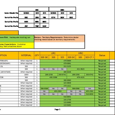
Rdsl Parts List For 320 Gc 320 And 323 Ver 8 Updated June 14 2018 Updated Lrc Serial No Prefix 3s495h
July 2020 3
Marcas2212 (1).pdf zm1h
August 2022 0
Data Pengeluaran Sgp - Data Sgp Lengkap - Data Sgp - Data Paito Sgp(1) 1rr39
October 2021 0