Autoclave - C17plus - Operating Instructions 3x2l5w
This document was ed by and they confirmed that they have the permission to share it. If you are author or own the copyright of this book, please report to us by using this report form. Report 3i3n4
Overview 26281t
& View Autoclave - C17plus - Operating Instructions as PDF for free.
More details 6y5l6z
- Words: 19,719
- Pages: 93
C-17PLUS C-22PLUS C-28PLUS Operating instructions
REVISIONS The following table lists subsequent editions/revisions of the manual. The “Description” field brief explains the subject of the latest revision. Code
Rev.
Date
97050776
0
11-2014
Description First issue (translation from the original in Italian)
TABLE OF CONTENTS INTRODUCTION.....................................................................................................................................1 Symbols used in the manual................................................................................................................................ 1 Symbols on equipment........................................................................................................................................... 1 APPLICABLE EUROPEAN DIRECTIVES............................................................................................................................. 1 intended use.................................................................................................................................................................... 1 Important notes.......................................................................................................................................................2 PURPOSE OF THE MANUAL .............................................................................................................................................. 2 GENERAL WARNINGS......................................................................................................................................................... 2
CONTENTS OF THE PACKAGE............................................................................................................3 Dimensions and weight................................................................................................................................................ 3 DESCRIPTION OF THE CONTENTS................................................................................................................................... 3 HANDLING THE PRODUCT................................................................................................................................................. 4
PRODUCT INTRODUCTION..................................................................................................................5 Introduction................................................................................................................................................................... 5 General Characteristics........................................................................................................................................... 5 FRONT................................................................................................................................................................................... 6 REAR..................................................................................................................................................................................... 7 LCD ICONS........................................................................................................................................................................... 8 Operating cycle example........................................................................................................................................... 9
INSTALLATION.....................................................................................................................................10 Introduction................................................................................................................................................................. 10 Compartment dimensions for built-in installations..................................................................................... 10 General installation precautions ...................................................................................................................... 11 Electrical Connections........................................................................................................................................... 11 DIRECT CONNECTION TO A CENTRALized DRAINing point..................................................................................... 12
FIRST START-UP.................................................................................................................................13 Turning on the equipment........................................................................................................................................ 13 MAIN MENU ....................................................................................................................................................................... 14 Filling distilled water ............................................................................................................................................. 15 Manual filling..........................................................................................................................................................15 Automatic filling....................................................................................................................................................15
CONFIGURATION................................................................................................................................16 SETTINGS........................................................................................................................................................................... 16
PREPARING THE MATERIAL..............................................................................................................24 Introduction................................................................................................................................................................. 24 Treating the material before sterilization..................................................................................................... 24 arranging the load.................................................................................................................................................... 25
STERILIZATION CYCLES ..................................................................................................................27 EXTRA DRYING....................................................................................................................................29 I
PROGRAMMED STARTING.................................................................................................................30 RUNNING THE CYCLE....................................................................................................................................................... 31 RESULT OF THE cycle.................................................................................................................................................... 31 DOOR OPENING AT CYCLE END...................................................................................................................................... 31 MATERIAL STORAGE......................................................................................................................................................... 32
TEST PROGRAMS...............................................................................................................................33 Introduction................................................................................................................................................................. 33 cycle Helix Test/B&D................................................................................................................................................... 33 cycle VACUUM TEST...................................................................................................................................................... 35 VACUUM TEST + Helix Test/B&D cycle..................................................................................................................... 36 H2O TEST........................................................................................................................................................................... 36 DOOR OPENING................................................................................................................................................................ 37 USED WATER DRAIN......................................................................................................................................................... 38 Detaching the pipe.................................................................................................................................................38 MANUAL INTERRUPTION ................................................................................................................................................. 38
DATA MANAGEMENT..........................................................................................................................39 APPendix – Technical Characteristics................................................................................50 SUMMARY TABLE.............................................................................................................................................................. 50 Safety Devices.............................................................................................................................................................. 51 Water supply characteristics.............................................................................................................................. 52
APPENDIX – PROGRAMS...................................................................................................................53 INTRODUCTION................................................................................................................................................................. 53 Program Summary Table – C-17 PLUS..................................................................................................................... 54 Program Summary Table – C-17 PLUS.................................................................................................................... 55 Program Summary Table – C-22 PLUS..................................................................................................................... 56 Program Summary Table – C-22 PLUS..................................................................................................................... 57 Program Summary Table – C-28 PLUS .................................................................................................................... 58 Program Summary Table – C-28 PLUS .................................................................................................................... 59 STERILIZATION PROGRAM DIAGRAM............................................................................................................................. 60 DIAGRAMS of THE TEST PROGRAMMES...................................................................................................................... 62 EXAMPLES OF PRINTED REPORTS................................................................................................................................ 63
APPENDIX – MAINTENANCE..............................................................................................................64 Introduction................................................................................................................................................................. 64 Ordinary Maintenance Program........................................................................................................................... 64 Scheduled Maintenance Messages................................................................................................................. 64 Sterilization cycle backup................................................................................................................................ 65 Maintenance Description ........................................................................................................................................ 66 Clean gasket and porthole.............................................................................................................................. 66 Clean external surfaces................................................................................................................................... 66 Clean sterilization chamber and accessories ........................................................................................ 66 Disinfect external surfaces............................................................................................................................ 66 Boiler filter cleaning......................................................................................................................................... 67 Door lock lubrication......................................................................................................................................... 67 Dust filter cleaning.............................................................................................................................................68 Replace the bacteriological filter.............................................................................................................. 68 Water tank cleaning............................................................................................................................................. 68 Boiler gasket replacement.............................................................................................................................. 68 Periodic sterilizer validation................................................................................................................................ 69 DISPOSAL at end-of-life.............................................................................................................................................. 69
APPENDIX – GENERAL PROBLEMS.................................................................................................70 Introduction................................................................................................................................................................. 70 IIII
Analysis and resolution of problems................................................................................................................ 70
APPENDIX – alarms.........................................................................................................................72 Introduction................................................................................................................................................................. 72 alarm intervention..................................................................................................................................................... 72 Alarm during a cycle............................................................................................................................................ 72 SYSTEM RESET................................................................................................................................................................. 73 Alarm Codes................................................................................................................................................................... 74 Analysis and resolution of problems................................................................................................................ 78
APPENDIX – DELETION PIN...................................................................................................86 APPENDIX – ACCESSORIES..............................................................................................................87 PRINTER CONNECTION..............................................................................................................................................88
APPENDIX – TECHNICAL .................................................................................................89
III
INTRODUCTION
Dear Customer Thank you for choosing this product. We hope that you will find it completely satisfactory. This manual describes all procedures for the correct use of the device and instructions for deriving the full benefit from its features. In any case, we will be available to provide explanations and to receive any suggestions you may have for improving our products or services.
Symbols used in the manual
NOTE PAY SPECIAL ATTENTION TO PARAGRAPHS INDICATED BY THE POINTING FINGER. WARNING This symbol indicates a potential danger of injury. Follow the procedures described in the manual to avoid injuring the and/or others. DANGER This symbol indicates a potential danger of property damage. Follows the instructions in the manual to prevent potential damage to materials, equipment or other property. DANGER This symbol indicates a potential danger due to high temperature. The material the STERILIZER is composed of must be disposed according to the directive 2002/96/CEE
Symbols on equipment
Potenzial hazard due to high temperature. Equipment in accordance with applicable directives. Symbol for disposal in accordante with Directive 2002/95 EC, 2002/96/ EC, and 2003/108/ EC. Consult the manual.
APPLICABLE EUROPEAN DIRECTIVES
The product described in this manual is manufactured in accordance with the highest safety standards and doesn't represent any danger for the operator if used according to the following instructions. The product is in accordance with the following European Directive as applicable: 2006/95/CE, for the approximation to the legislation of the States related to low voltage equipment. 2004/108/CE, for the approximation to the legislation of the States related to the electromagnetic compatibility; 93/42CEE
intended use
and subsequent changes, concerning the medical devices.
The product described in this manual is intended exclusively for sterilization of reusable surgical instruments and materials. DEVICE INTENDED FOR PROFESSIONAL USE AND NOT FOR SALE TO THE GENERAL PUBLIC. WARNING The device must only be used by qualified personnel. It may not be used or handled by inexpert and/or unauthorized personnel for any reason. This device must not be used for the sterilization of fluids, liquids or pharmaceutical products. WARNING THE STERILIZER IS NOT A MOBILE OR PORTABLE DEVICE.
1
Important notes
PURPOSE OF THE MANUAL
NOTE THE MANUAL INFORMATION ARE SUBJECT TO CHANGES WITHOUT ANY NOTICE. THE MANUFACTURER IS NOT RESPONSIBLE FOR DIRECT, INDIRECT OR ACCIDENTAL DAMAGE RESULTING FROM OR RELATING TO THE PROVISION OR USE OF THIS INFORMATION. THIS DOCUMENT MAY NOT BE REPRODUCED, ADAPTED OR TRANSLATED, IN PART OR IN FULL, WITHOUT THE PRIOR WRITTEN PERMISSION OF THE MANUFACTURER. The purpose of this manual is to provide instructions for: –– –– –– ––
becoming generally familiar with the product; its correct installation and configuration; its safe, efficient use; handling materials before and after sterilization. Its APPENDIXs also provide:
–– –– –– –– ––
the product's general technical specifications; sterilization program specifications; maintenance; troubleshooting; a variety of other documentation.
When using this product, always follow the instructions in the manual and never use for anything other than its intended purpose. WARNING The is responsible for all legal requirements related to the installation and use of this product. The manufacturer will not be responsible for any breakage, malfunctions, property damage or injury in the event that the product is not installed or used correctly. Please observe the following precautions in order to avoid injury or property damage: –– Use ONLY distilled water of high quality. WARNING The use of water of inadequate quality can severely damage the device. See Appendix Technical Characteristics in this regard.
GENERAL WARNINGS
–– –– –– ––
Do not pour water or other liquids on the device; Do not pour inflammable substances on the device; Do not use the device in the presence of gas or explosive or inflammable vapors; Before performing any maintenance or cleaning, ALWAYS DISCONNECT the electricity. DANGER Whenever it is not possible to disconnect the electricity to the device, or if the external power grid switch is far away or, at any rate, not visible to the maintainer, place a WORK IN PROGRESS sign on the external power grid switch after turning it OFF.
–– Make sure the electrical system is grounded conforming to current laws and/or standards; –– Do not remove any label or nameplate from the device; request new ones, if necessary. –– Use only original replacement parts. WARNING The failure to observe the above, releases the manufacturer from all liability.
2
CONTENTS OF THE PACKAGE Dimensions and weight
NOTE CHECK THE INTEGRITY OF THE PACKAGE UPON RECEIPT. Once the package is opened, check that: –– the supply matches the specifications of the order (see the accompanying document); –– that there is no obvious product damage;
A
Dimensions and weight A. Height
600 mm
B. Width
600 mm
C. Depth
700 mm
Total weight
68 kg
B
C
NOTE IN THE CASE OF A WRONG PRODUCT, MISSING PARTS OR ANY TYPE OF DAMAGE, IMMEDIATELY PROVIDE A DETAILED DESCRIPTION TO THE RESELLER AND THE TRANSPORTER THAT MADE THE DELIVERY.
DESCRIPTION OF THE CONTENTS
6
11 1
5
7
4
8
2
9
10 3
In addition to the steriliser, the package contains: 1. 2. 3. 4. 5. 6. 7. 8. 9. 10. 11.
No. 5 stainless steel wire instrument tray; Stainless steel wire tray ; Operating documentation (with CD-ROM); Lubricant for door lock mechanism; Tray extractor; Extra bacteriological filter; Rubber hose with quick-coupling for manual water drainage; 1/8” swivel angular connector; 5mm socket wrench for manual door unlocking; Plastic tube for direct water drainage with fastening clamp; Rear spacers
Where possible, the packaged product must be handled using suitable mechanical means (forklift truck, transpallet, etc.) and following the instructions shown on the package.
3
HANDLING THE PRODUCT
In the case of manual handling, the product must be lifted by two persons using the handles cut in the side of the box. Once the sterilizer has been taken out of the box, it must be lifted by two persons using appropriate means and possibly handled with a lift truck or similar. WARNING We recommend that the device be transported and stored at a temperature no lower than 5 °C. Prolonged exposure to low temperature an damage the product. NOTE KEEP THE ORIGINAL PACKAGING AND USE IT WHENEVER THE DEVICE IS TO BE TRANSPORTED. THE USE OF DIFFERENT PACKAGING COULD DAMAGE THE PRODUCT DURING SHIPMENT. DANGER Before transport, leave the device turned-off for about 30 minutes after the last program finishes and drain the distilled water and used water tanks so that the all the hot internal parts will have time to cool.
4
PRODUCT INTRODUCTION Introduction
The C-17PLUS, C-22PLUS, C-28PLUS series sterilisers are the revolutionary products offered by Castellini in the field of small water steam sterilisers, equipped with type B (EN 13060) cycles, as well as the new point of reference with respect to safety, performance, flexibility and ease of use. It is a sophisticated but, at the same time, easy to use device that, thanks to its wide range of configuration options and patented operating devices, satisfies every need for sterilizing medical devices, guaranteeing the maximum performance under all conditions. It also features a better way of relating to s who, rather than having to adapt to the machine and its characteristics, are able to "converse" with it and configure it to meet their own needs. Thanks to its remarkable ease of use, small size and pleasant appearance, it is the ideal partner for all professional who demand the maximum sterilization safety.
General Characteristics
A C-17PLUS, C-22PLUS, C-28PLUS series steriliser is an electronic water steam steriliser that is entirely operated by a micro-processor with a large, printed stainless steel sterilisation chamber. It is characterized by an advanced fractionated vacuum system for the complete removal of air, even from hollow, porous materials, and an effective final vacuum drying phase capable of eliminating all traces of humidity from any load. Its exclusive steam generation system, effective plumbing circuit and electronic management (supplemented by high-precision sensors) guarantees high process execution speeds and excellent thermodynamic parameter stability. Moreover, its Process Evaluation System constantly monitors all the machine's “vital” parameters in real-time, guaranteeing absolute safety and a perfect result. It offers s 6 sterilization programs (of which one completely PRESETble), all equipped with customizable, optimized drying for the fast, effective sterilization of the various types of loads (instruments and materials) used in a medical environment. All the cycles are directly selectable via the LCD touchscreen, which also allows complete device configuration according to the ’s requirements. For the first time, a lighting system is available for the working area in front of the sterilization chamber, which makes the daily operations ever easier and more comfortable. Please refer to the chapter, “Configuration” for more detail. Like in the best Castellini tradition, also the new range of C-17PLUS, C-22PLUS, C-28PLUS autoclaves has the most complete, sophisticated and advanced safety systems available today to guarantee the against any electrical, mechanical, thermal or biological malfunction. NOTE For the description of the safety devices, refer to the Appendix Technical Characteristics.
5
FRONT
LCD touchscreen control
Door
On/Off switch
Dust filter
Sterilization chamber
Bacteriological filter
Door closing system
Water drain filter
Distilled water top-up quickcoupling Distilled water quick-coupling only) Dust filter Used water drain quick connector Door
6
tank drain (SERVICE
REAR
Rear spacer fastening slots
Heat exchanger
Connection for Direct water drainage Connection for automatic distilled water filling (only for PURE 100/500 and the automatic filling accessory kit) Dust filter Data label Ethernet cable connection (max length 29 m) Serial cable connection Automatic filling electrical connection (only for PURE 100/500 and the automatic filling accessory kit) Mains fuses Power cable connection
7
LCD ICONS TEST CYCLES
TIME AND DATE
SETUP
DATA MANAGEMENT
TEST STERILIZATION CYCLES
MOST FREQUENTLY RUN TEST
MOST FREQUENTLY RUN CYCLE
DOOR UNLOCK
Sterilizer setting management
Data and information management
TEST
Sterilization cycle menu
TEST
Test cycle menu
NOTE OTHER PARTICULAR SYMBOLS RELATED TO THE VARIOUS CONDITIONS OF USE ARE DESCRIBED IN DETAIL IN THE RELATIVE PARAGRAPHS.
8
Operating cycle example
The C-17PLUS, C-22PLUS, C-28PLUS series sterilisation programme can be effectively described as a succession of phases, each one with a very precise objective. For example, the standard program (cycle B, 134°C - 4’): after loading the material in the chamber, closing the door, selecting the program and starting the cycle (after locking the door opening mechanism), the following sequence will be suggested (see the graph below): 1. preheating the generator and sterilization chamber; 2. removing the air and penetration of the material by steam through a series of vacuum (extraction of the fluid from the sterilization chamber) and pressure(injection of steam into the chamber) phases; 3. raising the pressure, with the consequent increase in the temperature of the steam, until reaching the conditions required for sterilization (in the example, 134 °C); 4. stabilizing the pressure and temperature; 5. sterilizing for the required time (in the example, 4 minutes); 6. depressurizing the sterilization chamber; 7. vacuum-drying phase; 8. ventilating the load with sterile air; 9. bringing the pressure of the sterilization chamber back to the atmospheric level. Having reached this last phase, you can unlock the door and remove the load from the sterilization chamber. It should be emphasized that phases 1, 3, 4, 6 and 9 are identical in all cycles, with slight variations of duration that are solely dependent on the quantity and consistency of the load and the heating conditions of the sterilizer while phases 2, 5, 7 and 8 clearly vary their configuration and/ or duration on the basis of the cycle selected (and, as a consequence, the type of load) and the choices made by the .
P res s ure (bar)
P R OC E SS 2.10 2.00
1.00
Time (min) 0.00
-0.80 SINGLE VACUUM PULSE
VACUUM DRYING
NOTE PLEASE REFER TO APPENDIX PROGRAMS FOR MORE DETAIL.
9
INSTALLATION Introduction
The first and fundamental step in achieving good sterilizer operation, long life and complete use of its features is a correct, careful installation. Moreover, this precaution will avoid the danger of physical injury or property damage, not to mention malfunctions and damage to the machine. So, please follow the instructions in this chapter scrupulously. NOTE CUSTOMER (SEE APPENDIX) WILL ANSWER YOUR QUESTIONS AND PROVIDE ADDITIONAL INFORMATION. THE STERILIZER HAS ED ALL REQUIRED INSPECTIONS BEFORE BEING PLACED ON THE MARKET. IT DOES NOT REQUIRE ANY ADDITIONAL CALIBRATION BEFORE BEING PLACED IN SERVICE. Dimensions and weight A. Height (total)
C-17PLUS
C-22PLUS
500 mm
B. Width (total) C. Depth (excluding rear connections)
480 mm
Note: the sterilizer can however be positioned on a surface only 550mm deep
600 mm
Total weight
C-28PLUS
B
A
50 kg
55 kg
C
60 kg
Electricity. The electrical system to which the sterilizer will be connected must be suitably dimensioned based on the electrical characteristics of the device.
Compartment dimensions for built-in installations
When installing the sterilizer inside a cabinet, you must provide adequate space all around the device to provide effective ventilation as well as a large enough opening in the back that, in addition to allowing the age of the power cord will also provide an adequate air flow and the consequent optimum cooling of the heat exchanger.
C
B
A
The compartment where the steriliser will be kept must have the following minimum dimensions:
Dimensions A. Height B. Width
17-22-28 lt 500 mm with FRONT FILLING KIT 670 mm with FILLING FROM THE TOP (door) 600 mm
WARNING Compartment dimensions less than those shown may compromise the correct circulation of air around the device and may not provide adequate cooling, with the consequent deterioration of performance and/or possible damage. NOTE IF THE FILLING AND DRAINAGE DOORS ARE NOT ACCESSIBLE FROM THE TOP AFTER THE DEVICE HAS BEEN BUILT IN, IT IS ADVISABLE TO USE THE FRONT ATTACHMENTS (FRONT FILLING KIT). IF THE MAIN SWITCH IS INACCESSIBLE WHEN INSTALLED IN THE COMPARTMENT, USE AN ELECTRIC PLUG THAT INCORPORATES AN ON/OFF SWITCH. DO NOT REMOVE THE UPPER COVER OR ANY OTHER EXTERNAL PART. WHEN INSTALLED IN THE COMPARTMENT, THE DEVICE MUST BE COMPLETE WITH ALL ITS PARTS. PLEASE REFER TO APPENDIX TECHNICAL CHARACTERISTICS FOR COMPLETE TECHNICAL DATA.
10
General installation precautions
Obey the following warnings for the correct operation of the device and/or to avoid risky situations: –– Install the sterilizer on a flat and perfectly horizontal surface. –– Make sure that the surface is strong enough to the equipment weight (about 60 kg); –– Leave adequate space for ventilation (at least 10 cm on each side) all around the sterilizer, especially in back. –– If the device is built-in to a cabinet, be sure to respect the warnings in the preceding paragraph, avoiding an obstructions to the air intake; –– Do not install the sterilizer near tubs, sinks or similar places, to avoid with water or liquids. This could cause short circuits and/or potentially dangerous situations for the operator; –– Do not install the sterilizer in a place that is excessively humid or poorly ventilated; –– Do not install the machine were there is gas or inflammable and/or explosive vapors; –– Install the device so that the power cord is not bent or crushed. It must run freely all the way to the socket. –– Install the device that any external fill/drain tubing is not bent or crushed. They must run freely to the drain tank. This information is shown on the back of the machine.
Electrical Connections
The sterilizer's must be connected to a socket of the electrical system of adequate capacity for the device's absorption and ground provided, in conformity with current laws and/or standards. The socket must be suitably protected by a breaker having the following characteristics: –– Nominal current In
–– Differential current IDn
16 A 0,03 A
WARNING THE MANUFACTURER WILL NOT BE LIABLE FOR DAMAGES CAUSED BY INSTALLING THE STERILIZER ON AN INADEQUATE ELECTRICAL SYSTEM AND/OR NOT EQUIPPED WITH A GROUND. NOTE ALWAYS CONNECT THE POWER CORD DIRECTLY TO THE SOCKET. DO NOT USE EXTENSION CORDS, ADAPTERS OR OTHER ACCESSORIES.
11
DIRECT CONNECTION TO A CENTRALized DRAINing point
–– Remove the cap holding clip on the rear of the autoclave. –– Fit the plastic tube on the elbow union (provided). –– Fit the union and then refit the clip. –– Fasten the clip provided to the drain siphon. –– Cut the hose to the right length and insert its free end into the centralized draining connector locking it with the dedicated ring nut. NOTE MAKE SURE THE TUBE IS NOT BENT, CRUSHED OR OBSTRUCTED IN ANY WAY. The following diagram provides an indicative arrangement of the components:
Drain siphon plane To the centralized draining point
Clamp
NOTE THE CONNECTION POINT TO THE CENTRAL DRAIN MUST BE LOWER THAN THE STERILIZER'S SURFACE. OTHERWISE, THE TANK MAY NOT EMPTY CORRECTLY. NOTE FOR AUTOMATIC FILLING SYSTEMS (PUMP, PURE 100, PURE 500, EV7) THE DIRECT DRAIN MUST ALWAYS BE CONNECTED. THIS ACTS AS AN OVERFLOW, AND, IF FOR SOME REASON, THE FILLING SYSTEM DOES NOT STOP, THE WATER SEEPS FROM THE FEED TANK INTO THE DRAIN TANK AND FLOWS OUT THE DIRECT DRAIN, THUS PREVENTING FLOODING.
12
FIRST START-UP
Once the sterilizer has correctly been installed, turn it on with the main switch on the right-hand side of the machine.
Turning on the equipment
WARNING DO NOT TURN ON THE STERILIZER, IF USB KEY IS INSERTED.
When the sterilizer is turned on, the following page appears:
CASTELLINI 80%
13
MAIN MENU
At first start, the autoclave guides you through configuration: select the language, date and time.
Language
Italiano English Deutsch
GMT +1
hh mm
Date and Time DD MM YYYY
05
15
30
06
2013
Once the start procedure has been completed, the main menu shown below appears on the display.
TEST The device waits for selection of the desired program (see section “Program Selection”). DANGER To prevent burns, be careful not to touch the sterilization chamber, the chamber equipment or the inside of the door with bare hands.
14
Filling distilled water
The first time the sterilizer is used, and later when the MIN water level indicator comes on, you will have to fill, or top-off, the internal distilled water tank. Open the loading door.
Manual filling
Pour in water taking care not to exceed the maximum level (MAX) indicated inside the tank. Close the door. Be carefulnot to spill any water on the machine, and if so, immediately dry it off.
BEEP
WARNING THE TANK MUST BE FILLED BEFORE THE CYCLE STARTS OR AFTER ITS COMPLETION. DO NOT OPEN THE TANK DOORS DURING CYCLE EXECUTION IN ORDER TO PREVENT WATER LEAKS. Automatic filling
Refer to the Appendix "ACCESSORIES".
15
CONFIGURATION
The C-17PLUS, C-22PLUS, C-28PLUS series offers a wide range of customisation options. The can thus configure the device according to need, adapting the performance based on, for example, the type of activity carried out, the type of material to be sterilized and the frequency of use. Using the configuration program, the can set a series of options available in -friendly menus. NOTE USE THE SETUP PROGRAM WHENEVER NECESSARY. A CORRECTLY PERSONALIZED DEVICE PROVIDES THE BEST PERFORMANCE AND THE MOST SATISFACTORY USE.
CUSTOMER (SEE APPENDIX) IS AVAILABLE TO HELP S BY PROVIDING SUGGESTIONS OR ADVICE ON THE BEST WAY TO USES THE OPTIONS IN THE SETUP PROGRAM.
SETTINGS
To access the configuration program, tap the button shown in the figure.
TEST
Language
Date and Time
Standby
Preferences
Language
Date and Time
Standby
Preferences
LANGUAGE
Select the desired language using the scroll arrows. Language
Italiano English Deutsch
16
DATE AND TIME
Language
Date and Time
Standby
Preferences
Use the cursors shown in the figure to adjust the hours, minutes and display settings. Tap
to confirm the selection.
GMT +1
hh mm
Date and Time DD MM YYYY
05
15
time zone hours minutes
30
day
month
06
2013
year
17
Language
Date and Time
Standby
Preferences
MANAGEMENT At first use, create the (identified with an *) following the indications in the figure below. Enter the name and PIN in the relative fields. Tap to confirm. Nico_ .,- 1 ghi 4 pqrs 7
Nicola* def 3
abc 2 jkl 5
mno 6
tuv 8
wxyz 9
1547
0
After registration of the , the following page is displayed when accessing management. Select the from the list.
Nicola*
Enter the PIN. Tap
to confirm. Nicola*
1547
NOTE IF THE ENTERS THE PIN INCORRECTLY THREE TIMES, THE SYSTEM IS LOCKED AND THE UNLOCKING PROCEDURE DESCRIBED IN THE APPENDIX “ PIN RESET” NEEDS TO BE USED
The can decide whether the sterilizer should ask the generic for a PIN at the start of the cycle (PIN START) and/or at the end of the cycle (PIN END). Tap ON to activate the PIN request or OFF to deactivate it. Nicola*
PIN START
+
New
PIN END
Tapping NEW , the can create a new generic following the instructions described above. Tapping LIST, you access the list.
18
Nicola*
Nicola* Marco
Tapping the
button, you obtain the data relating to the highlighted: Nicola* PIN change
ID: 0003 Name: Marco Rossi creation date: 12/02/12 Cycles run: xxx/yyy
The can change the PIN of the highlighted in the list by directly entering the new PIN or promote the to . Tapping the
button, the can delete the highlighted in the list. Nicola* Warning Are you sure you want to delete the Nicola* "Marco"?
Marco
Confirm deletion by tapping OK or the
OK
button to go back.
Tapping the button, the can select the cycles the selected is authorised to run by tapping the corresponding icons. Marco
B 134
B 121
S 134
S 134
Solid
Hollow
B 134
19
MANAGEMENT After registration of the generic s, the following page is displayed when accessing management. Select the pertinent generic from the list.
Nicola* Marco Chiara
Enter the PIN. Marco
1547
Generic s can change their PIN by directly entering the new PIN, view the cycles they are authorised to run and view their data. Marco PIN change
ID: 0003 Nom: Marco Rossi Date création utilisateur: 12/02/12 Cycles effectués:xxx/yyy
The cycle list is read-only for generic s (not ). Marco
20
B 134
B 121
S 134
S 134
B 134
STANDBY Language
Date and Time
Standby
Preferences
30
Tap the ON/OFF icons to activate or deactivate sterilization chamber heating during standby. Use the cursors to set the heating off delay. Tap
to confirm.
PREFERENCES Language
Date and Time
Standby
Preferences
Selecting the preferences icon, the following page is displayed. Preferences
H2O filling
Unit of measure
Display
21
H2O filling
Preferences
H2O filling
Unità di misura
Display
When connecting the automatic filling system, the sterilizer asks you to identify the type of device actually connected by tapping the corresponding button.
Manual filling
Pure 100 Pure 500
If connecting the filling system when the sterilizer is off, access the menu via the configuration program and manually select the correct option. NOTE THIS MENU CAN ALSO BE USED TO TEMPORARILY DEACTIVATE THE AUTOMATIC FILLING SYSTEM (FILTERS EXHAUSTED, FAULT, ETC.) AND GO TO MANUAL TANK FILLING.
UNIT OF MEASURE
Preferences
H2O filling
Unit of measure
Schermo
Set the desired units of measure (temperature, pressure), the time (12 or 24 hours) and the date using the cursors shown in the figure. Unit of measure °C
bar
temperature pressure
22
12h
time
dd:mm:yy
date
SCREEN Preferences
H2O filling
Unit of measure
Display
Tapping the icon shown in the figure above, you can select the screen and LED bar settings. Selecting White or Blue, you set the main theme colour. The three cursors on the left-hand side respectively adjust: - LED bar off timeout - screen brightness - Screensaver activation timeout (the current time is displayed). Display
20’
SERVICE
15’
LED brightness
60%
screensaver
This menu is reserved for Technical Service.
Language
Date and Time
Standby
Preferences
It may only be used by an authorised technician.
23
PREPARING THE MATERIAL
First of all, it should be recalled that, when handling and managing contaminated material, it is a good idea to take the following precautions:
Introduction
–– Clean your gloved hands with a germicide detergent;
–– Wear rubber gloves of adequate thickness; –– Always carry the instruments on a tray; –– Never carry them in your hands; –– Protect your hands from with any sharp points or edges; this will avoid the risk of contracting a dangerous infection; –– Immediately remove any article that does not need to be sterilized or that is not capable of withstanding the process; –– Carefully wash your still gloved hands when done handling non-sterile material. All materials and/or instruments to be sterilized must be perfectly clean, without any type of residue (deposits of organic/inorganic material, fragments of paper, cotton/gauze pads, lime, etc.). NOTE IN ADDITION TO CAUSING PROBLEMS DURING STERILIZATION, THE FAILURE TO CLEAN AND REMOVE RESIDUE CAN DAMAGE THE INSTRUMENTS AND/OR THE STERILIZER, ITSELF.
Treating the material before sterilization
An effective cleaning consists of the following: 1. Rinse the instruments under running water immediately after use; 2. Separate metal instruments by type of material (carbon steel, stainless steel, brass, aluminum, chromium, etc.), to avoid electrolytic oxidation-reduction; 3. Wash in an ultrasound cleaner using a mixture of water and germicidal solution, carefully following the manufacturer's recommendations. 4. For best results, use a detergent specifically designed for ultrasound washing, with a neutral pH. NOTE SOLUTIONS CONTAINING PHENOLS OR QUATERNARY AMMONIA COMPOUNDS CAN CAUSE CORROSION ON INSTRUMENTS AND THE METAL PARTS OF ULTRASOUND DEVICES. 5. After washing, carefully rinse the instruments and make sure that residues have been completely eliminated; if necessary, repeat the washing cycle or clean manually. NOTE TO AVOID THE FORMATION OF LIME SPOTS, RINSE WITH DEIONIZED OR DISTILLED WATER, IF POSSIBLE. WHENEVER VERY HARD TAP WATER IS USED, WE RECOMMEND ALWAYS DRYING THE INSTRUMENTS. For handles (turbines, contra-angles, etc.), supplement the above with treatment in suitable dedicated devices that provide effective internal cleaning (occasionally including lubrication). NOTE THE END OF THE STERILIZATION PROGRAM, TO LUBRICATE THE INTERNAL HANDLE MECHANISMS USING THE SPECIAL STERILE OIL. BY TAKING THESE PRECAUTIONS, THE INSTRUMENTS USEFUL LIFE WILL NOT BE REDUCED IN ANY WAY. WARNING CONSULT THE INSTRUCTIONS PROVIDED BY THE MANUFACTURER OF THE INSTRUMENT/MATERIAL TO BE STERILIZED BEFORE SUBJECTING IT TO AUTOCLAVE TREATMENT, CHECKING FOR ANY INCOMPATIBILITIES. SCRUPULOUSLY FOLLOW THE METHODS OF USING DETERGENTS OR DISINFECTANTS AND THE USAGE INSTRUCTIONS OF THE AUTOMATIC DEVICES FOR WASHING AND/OR LUBRICATING THEM.
24
On the other, as regards textile material (or porous, in general), such as smocks, napkins, caps and other, carefully wash and then dry them before treating them in the autoclave. NOTE DO NOT USE DETERGENTS WITH A HIGH CONTENT OF CHLORINE AND/ OR PHOSPHATES. DO NOT BLEACH WITH CHLORINE-BASED PRODUCTS. THESE SUBSTANCES CAN DAMAGE THE TRAY S, TRAYS AND ANY METAL INSTRUMENTS THAT MAY BE PRESENT IN THE STERILIZATION CHAMBER.
Follow the instructions below for the most efficient sterilization process, preserve the material and increase its useful life.
arranging the load
General notes for positioning on trays: –– Arrange instruments made of different metals (stainless steel, tempered steel, aluminum, etc.) on different trays or well separated from each other; –– In the case of instruments not made of stainless steel, place a paper sterilization napkin or a muslin cloth between the tray and the tool, avoiding direct between the two different materials; –– In any case, arrange the objects sufficiently distant from each other that they will remain so for the entire sterilization cycle; –– Make sure that all instruments are sterilized in an open position;
OK
–– Position cutting instruments, (scissors, scalpels, etc.) so they can not come into with each other during sterilization; if necessary, use a cotton or gauze cloth to isolate and protect them; –– Arrange recipients (glasses, cups, test tubes, etc.) resting on their side, or upended, so avoid pooling water; –– Do not load trays beyond their indicated limit (see Appendix A). –– Since this value is understood to be the maximum allowed limit, it can be excessive in some cases, so always use common sense. –– Do not stack trays or put them in direct with the walls of the sterilization chamber.
OK
–– Always use the tray provided. –– To insert and extract trays from the sterilization chamber, always use the extractor provided. NOTE PLACE A CHEMICAL STERILIZATION INDICATOR ON EVERY TRAY TO INDICATE THAT THE PROCESS HAS OCCURRED: THIS AVOIDS USELESSLY REPROCESSING THE SAME LOAD OR, WORSE, USING NON-STERILIZED MATERIAL. IF PROCESSING WRAPPED MATERIAL, PLACE THE INDICATOR INSIDE ONE OF THE WRAPPINGS.
25
Notes for rubber and plastic tubing OK
– Always rinse before use with pyrogen-free water; do not dry them; – Arrange the tubing on the tray so that their ends are not obstructed or crushed. – Do not bend or wind them, but allow them to lie as straight as possible.
Notes for packets and packages
OK
– Arrange packages side-by-side, suitably spaced and absolutely not piled, to avoid their coming in with the walls of the chamber. – Whenever it is necessary to wrap particular objects, always use suitably porous material (sterilization paper, muslin napkins, etc.), closing the wrapping with autoclave adhesive tape.
Notes for wrapped material
OK
– Wrap instruments individually or, when more than one instrument are placed in the same wrapping, make sure that they are made of the same metal; – Seal the wrapping with adhesive tape for autoclaves or heat-sealing machines. – Do not use staples, pins or other fasteners since they can compromise the maintenance of sterility; – Arrange the envelopes so as to avoid forming air pockets that obstruct the correct penetration and removal of the steam. – Orient the envelopes so as to leave the plastic side up and the paper side down (tray side). – In any case, check that they are correctly positioned, turning them over, if necessary. – If possible, place the envelopes edgewise to the tray, with a suitable . –– Never superimpose envelopes on top of each other. WARNING If longer storage is recommended, always pack the instruments using packaging materials conform to EN 868. SEE THE CHAPTER, “PRESERVING STERILIZED MATERIAL”. A sterilization cycle consists of a determined number of phases.
Program selection is fundamental for a successful sterilization process. Since each instrument, or material in general, has different shape, consistency and properties, it is important to identify the most suitable program for it, both for preserving its physical characteristics (avoiding or, at any rate, limiting alterations) as well to guarantee the most effective sterilization. A guide to selection of the program suited to the load is given in the Appendix Programs.
26
STERILIZATION CYCLES
A sterilization cycle consists of a determined number of phases. The number and duration of the phases can differ for the programs, based on the type of air extraction, sterilization process and drying method. The electronic control system monitors the various phases, at the same time checking that the various parameters are respected; if any type of anomaly is encountered during the cycle, the program is immediately interrupted, generating an alarm identified by a code, with a relative message explaining the nature of the problem. With this type of control, when you select a suitable sterilization program, you are guaranteed perfect sterilization under any conditions. After inserting the load in the sterilization chamber (taking the precautions described in the section “Preparing the material to be sterilized”) , select the desired sterilization cycle as follows:
TEST
B 134
B 121
B 134 Prion
S 134 Solid
S 134 Hollow
Start the cycle by tapping the button shown in the figure. The cycle counter appears at the top left.
00056
4’
Process Time
1 bar
Nominal process pressure
28°C
Nominal process temperature
27
-DEFINED CYCLE To set the parameters, select the button as shown below:
B 121
B 134
B 134 Prion
S 134
S 134
Solid
Hollow
Tap and hold the button shown below to access the settings:
00056
settings
>3 S 4’
1 bar
28°C
Select the type of pre-vacuum, the process temperature, the exposure time and extra drying if necessary. settings
20 20
Once you have made the selections, tap the to the previous page. Tap the START button to start the -defined cycle.
00056
settings
4’
28
button to save the settings and go back
1 bar
28°C
EXTRA DRYING
To set the parameters, select the button as shown below:
B 121
B 134
B 134 Prion
S 134
S 134
Solid
Hollow
Tap and hold the button shown below:
00056
>3 S 4’
1 bar
28°C
Set the minutes of drying you want to add to the standard drying time.
20 The value set will appear next to the button. Start the cycle.
00056
+20 4’
1 bar
28°C
NOTE AT NEXT USE, JUST TAP THE EXTRA DRYING BUTTON TO ACTIVATE THE VALUES PREVIOUSLY SET.
29
PROGRAMMED STARTING
To set the parameters, select the button as shown below:
B 121
B 134
B 134 Prion
S 134
S 134
Solid
Hollow
Tap and hold the button shown below:
00056
>3 S 4’
1 bar
28°C
Set the time when you want to start the cycle selected.
1:30
15/12/13 09:30
The time set will appear next to the button. Tap the START button; the cycle will automatically start at the time set.
00056 15/12/13 09:30
4’
1 bar
28°C
NOTE AT NEXT USE, JUST TAP THE PROGRAMMED START BUTTON TO ACTIVATE THE VALUES PREVIOUSLY SET.
30
RUNNING THE CYCLE
Taking as example the most complete and significant sterilization cycle, i.e. the 134°C UNIVERSAL program, characterised by fractionated pre-vacuum, the cycle sequence is as follows: WARMING UP
PRE-HEATING
00:42
FIRST VACUUM PHASE FIRST PRESSURE RISE SECOND VACUUM PHASE 5SECOND PRESSURE RISE THIRD VACUUM PHASE THIRD PRESSURE RISE STERILIZATION STEAM DISCHARGE DRYING VENTILATION CYCLE COMPLETION
CYCLE COMPLETE
00:42
RESULT OF THE cycle
If the message "CYCLE COMPLETE" appears, it means that the cycle has completed correctly without any interruptions for alarms and that complete asepsis of the material is guaranteed.
DOOR OPENING AT CYCLE END
To open the sterilizer door, press the button shown in the figure:
CYCLE COMPLETE
00:42
31
MATERIAL STORAGE
The sterilized material must be adequately treated and stored to maintain its sterility over time, until its use. Inadequate storage can cause rapid recontamination. This leads to problems regardless of what you do since you will either be using recontaminated material (most of the time unconsciously), placing the and patient at risk, or you will have to run the sterilization cycle again, with an inevitable waste of time and resources. For this reason, we think it will be useful to provide several basic suggestions, leaving the operator the task of further study of specific texts.
Assuming that the sterilizer is located in a clean place, free of dust and not too damp, the following precautions should be taken when handling and/or carrying sterile material: 1. Remove the load from the sterilization chamber wearing gloves and a clean, or even better, sterilized smock. As an additional precaution, wear a protective mask on your face; 2. Rest the tray on a dry, suitably clean and disinfected surface. Take care to distance or, at any rate, separate the sterile material from the area where contaminated material is kept waiting to be sterilized; 3. Touch the material and/or instruments as little as possible, taking extreme care not to cut or damage the wrappings; 4. Let the instruments cool before any transport (and subsequent storage). If necessary for transport, transfer the material using dry, clean and disinfected containers. The containers must be closed or, if open, covered with clean cloths.
Sterile material waiting for used must be stored using the appropriate techniques. These will significantly slow recontamination: 1. Store the material and/or instruments in the protective wrappings that were used during sterilization. Do not wrap the instruments after sterilization since, in addition to being useless and completely senseless, is also potentially damaging; 2. Store the material in a dry, suitably clean and disinfected place, far from the area where infected material es. If possible, use closed compartments equipped with ultraviolet light; 3. Identify the sterile material by attaching the sterilization data (attaching a copy of the printed report or an adhesive label); 4. First use the material that has been stored the longest (FIFO, "First In First Out"). This results in material that is homogeneously stored, avoiding storing for too long, with the consequent risks. 5. Never store material for too long. In fact, do not overlook the fact that materials will tend to degrade and be recontaminated in a finite time, even when the above instructions are followed. NOTE Consult the specifications provided by the manufacturer of the packaging material relative to the maximum allowed storage time. In the absence of appropriate instructions, do not exceed the following storage periods: Basket with sealing ring or container without gasket Container with filter and gasket or container with valves. Single-ply “Medical Grade” paper Double-ply “Medical Grade” paper (orthogonal) Polyester / polypropylene paper covering, single Polyester / polyproylene paper covering, double
1-2 days 30 days 1-2 days 30 days 30 days 60 days
The values indicated refer to material that has been properly stored.
32
TEST PROGRAMS
To protect the safety of s and patients, a fundamental process like sterilizing medical devices should be periodically checked.
Introduction
In this regard, the C-17PLUS, C-22PLUS, C-28PLUS series offer the possibility of easily and automatically executing two distinct test cycles: • Helix/B&D Test • Vacuum Test a program that executes the two tests combined is also available (Vacuum Test + B/D Test). There is also a further test to check the water quality: H2O TEST. Helix/BD Test is a cycle run at 134°C characterised by a sterilization phase that lasts a specific time (3.5 minutes); the cycle comprises the fractionated vacuum phases similar to those used in the UNIVERSAL cycles. Using an appropriate device, you can assess correct steam penetration into hollow loads. The cycle is also suitable to measure steam penetration into porous loads (Bowie & Dicktest pack).
cycle Helix Test/B&D
To select the Helix/B&D Test cycle, tap on the corresponding button and then on START.
TEST
00056
Helix / B&D Test
4’
1 bar
28°C
Helix / B&D Test PRE-HEATING
00:42
33
The test device (in accordance with EN 867-5 specifications) consists of a 1.5m-long PTFE tube with an inside diameter of 2mm to whose end a small hermetically-sealed screw cap is fastened, able to contain an appropriate chemical indicator. The other end of the tube is left free so that the steam can penetrate and you can assess its effectiveness. To conduct the test (with reference to EN 13060), insert the chemical indicator (consisting of a paper strip with a special reagent ink) in the device cap (always to be used perfectly dry). Tighten the cap in such a way that seepage through the gasket is not possible. NOTE The test device and the chemical indicators to execute the Helix/BD Test cycle are not provided with the sterilizer. For information in this regard, Customer Service (see Appendix). Place the device roughly in the middle of the central tray. Do not insert other material in the chamber. Close the door and start the cycle. The test cycle takes place with a succession of phases similar to those described for a normal sterilization cycle. At the end of the cycle, remove the test device from the chamber, open the cap and remove the indicator from its housing. If the steam has correctly penetrated, the ink will have completely changed its original colour over the entire length of the strip; if not (insufficient penetration), there will only be a partial colour change or even no change at all. NOTE Normally, the colour changes from a light colour (beige, yellow, etc.) to a dark colour (blue, violet or black). In any event, strictly follow the instructions and any additional technical details provided by the indicator manufacturer.
34
cycle VACUUM TEST
The Vacuum Test cycle allows testing perfect seal of the sterilizer hydraulic system. Measuring the variation of the degree of vacuum in a defined time-frame and comparing it with pre-established limit values, you can determine how good the seal of the sterilization chamber, tubes and the various interception devices is. To select the Vacuum Test cycle, select Vacuum Test using the arrows and confirm with OK.
TEST
00056
Vacuum Test
4’
1 bar
28°C
Vacuum Test VACUUM
00:42
35
The Vacuum Test program is run with the sterilization chamber empty, and only the trays and their s. NOTE RUN THE VACUUM TEST AS THE FIRST CYCLE AFTER POWERING-ON THE EQUIPMENT. A high chamber temperature affects the variation in the vacuum value measured during the test; the system is therefore programmed to prevent execution of the test when the operating conditions are inadequate. Close the door and start the program. The vacuum phase starts immediately and the pressure value (bar) and the countdown from the start of the test cycle is shown on the display. NOTE If the pressure variation exceeds the limit defined, the program is interrupted and an alarm message generated. For a complete description of the alarms, refer to the Appendix.
VACUUM TEST + Helix Test/B&D cycle
Selecting this option, you can run a VACUUM TEST cycle and a Helix Test/B&D cycle in sequence.
Vacuum Test
Helix / Test B&D
Vacuum Test + Test Helix
To this end, place the test device on the central tray without inserting other material. Close the door and start the cycle. The program will execute the two cycles in succession. Check the results as described in the previous paragraphs. NOTE The presence of the Helix Test device does not alter execution and the result of the Vacuum Test cycle.
H2O TEST
Selecting this option, you can test the water quality .
NOTE THE WATER CONDUCTIVITY IS AUTOMATICALLY MEASURED AT EACH STERILIZATION OR TEST CYCLE START.
36
DOOR OPENING
To open the autoclave door, hold down the button shown in the figure.
CYCLE COMPLETE
00:42
The door opens and stays ajar.
You can now manually open the door.
37
USED WATER DRAIN
Open the door and continue as follows: 1. Prepare a basin with a capacity of at least 4 litres in proximity of the sterilizer; place the free end of the drain tube provided in the basin. 2. Insert the other end of the tube in the female union beneath the chamber inlet (connector on the right) pushing down until you hear a click. 3. Completely empty out the tank and then press on the metal lever of the union and detach the tube quick-coupling.
Detaching the pipe
WARNING
MANUAL INTERRUPTION
DO NOT OPEN THE TANK DOORS DURING CYCLE EXECUTION IN ORDER TO PREVENT HOT WATER LEAKS OR SPURTS. The cycle can be interrupted manually by the operator at any time by holding down the button shown in the figure for three seconds. PRE-HEATING
00:42
>3 S
The command generates the error E999 as the cycle could not be completed correctly. NOTE If the cycle is interrupted during certain phases, an automatic cleaning procedure of the internal hydraulic circuit starts. For a complete description of the alarms, refer to the Appendix "Alarm Indications". WARNING After manually interrupting a program, DO NOT USE THE LOAD, AS STERILIZATION IS NOT GUARANTEED.
38
DATA MANAGEMENT
To access the DATA MANAGEMENT section, tap the corresponding icon. .
TEST
SYSTEM INFORMATION Selecting SYSTEM INFO, all the information relating to the sterilizer settings is displayed.
System information
Print management
Cycle
System information FW version: Autoclave code: Serial number: Language: St-by mode: Print: H2O filling: No. of cycles: / no. of complete cycles:
39
PRINT MANAGEMENT To set the parameters, select the button as shown below:
System inform.
Print manag.
Cycle
Print management
PRINT EXTENDED REPORT Tap the button to print the summary cycle report at the end of the process.
PRINT LABELS Tap the button to print the labels bearing the cycle data.
REPORT
print last cycle Tap the button to print the data of the last cycle set.
PRINT REPORT Tap the button to print the summary cycle report at the end of the process.
At the end of the cycle, when tapping the button indicated, the following page is displayed only if the printer is connected to the sterilizer and set for label printing (settable from print management). If not, the sterilizer automatically prints the report.
CYCLE COMPLETE
00:42
Label N.
15
Expiry
30
Select the number of labels to be printed at the end of the cycle and the sterilization expiry date. Use the arrow buttons to adjust the value. Tapping the green button (printer), the labels are printed; tapping the red button (crossed out printer), the labels are not printed.
40
CYCLE You can copy the data relating to the cycles run (stored in the internal memory of the sterilizer) to a USB key. To the sterilization/test cycle files, select the button as shown below.
Print manag.
System inform.
Cycle
Network config.
Before carrying out the operations, insert the USB key. NOTE NOTE: The USB key must be formatted using the FAT32 system file. If the USB key is not inserted, you are asked to do so. Cycle
Insert key…
The sterilization/test cycle files are in PDF format. You can select the number of cycles to be ed to the external memory. If the Last 10 or Last 100 option is selected, the programme will prompt to enter the number of the last cycle of the interval to .
Cycle
New Last Last 10
Cycle
in progress...
NOTE WHEN A PRESET VALUE IS EXCEEDED, THE SYSTEM WARNS YOU THAT YOU NEED TO MAKE A BACKUP OF THE DATA CONTAINED IN THE INTERNAL MEMORY. WARNING DO NOT TURN ON THE STERILIZER, IF USB KEY IS INSERTED.
41
ETHERNET The C-17PLUS, C-22PLUS, C-28PLUS series sterilizers can be connected to a local Ethernet network using the connector on the rear of the machine. Using a web browser (Internet Explorer, Chrome, Firefox etc.) from a PC or another device (tablet, smartphone, etc.) connected to the local network, you can, if you know the T-IP number assigned to the sterilizer, query it to check the operating status. From the sterilizer web page you can also the sterilization reports of the cycles executed in order to consult or store them. For network configuration, the sterilizer s the DH protocol. DH (Dynamic Host Configuration Protocol) is a T-IP protocol that allows a device to dialogue with a dedicated server and automatically receive the configuration data necessary to correctly communicate on the network. In small networks, the DH server functions are very often integrated in the router connected to the Internet. For correct configuration of the sterilizer, five types of use are described below: 1) Connection to a local network with DH server and sterilizer in automatic configuration. 2) Connection to a local network with DH server and sterilizer configured with static IP. 3) Connection to a local network manually configured with “static” IPs. 4) Direct connection via Ethernet cable between a sterilizer and a PC. 5) “Virtual point-to-point” connection between a sterilizer and a PC that uses the automatic DH configuration in a local network.
Local Ethernet network configurations To set the parameters, select the following option:
System inform.
Print manag.
Cycle
Network config.
42
1) Connection to a local network with DH server and sterilizer in automatic configuration
System inform.
Print manag.
Cycle
Network config.
Connect the sterilizer to the local Ethernet network using a network cable. View the Ethernet configuration page.
Ethernet configuration
123 . 567 . 789 . 012 DH
IP Adress
123 . 567 . 789 . 012 123
MAC:0004A39C7CF1
.
567
.
789
.
012
. Check that automatic DH configuration is selected With this selection, all the numerical fields on the page are disabled (they turn grey). With this setting, each time the sterilizer is turned on, it asks the network DH server for its configuration using the DH protocol. Based on the DH server configuration, the number assigned may vary each time the sterilizer is turned on. The T-IP number assigned to the sterilizer appears on the sky-blue bar at the top of the first page (Home). Type the number read on the sterilizer in the address field of the web browser.
43
The program will display the web page:
(in the example, the web page address is http://10.20.8.115) Normally, you can set the DH server so that the same IP number is always assigned to a given device or assign the same number to a certain device for a set period of time. For these settings, consult the instruction manuals of your local network DH server or Internet router. For these settings, you need to know the MAC address of the sterilizer, which is shown at the bottom left of the Ethernet configuration page. Ethernet configuration
123 . 567 . 789 . 012 DH
IP Adress
123 . 567 . 789 . 012 123
MAC:0004A39C7CF1
.
567
.
789
.
012
2) Connection to a local network with DH server and sterilizer configured with static IP. To avoid the inconvenience of having to frequently check the T-IP number dynamically assigned by a DH server, you can manually assign a fixed number belonging to the dynamic numbering of the local network. However, to prevent conflicts, it is essential that you: - Configure the DH server so that it does not assign the chosen number to other devices. or - Statically assign a number to the sterilizer outside the range assigned by the DH server. For the information necessary for a correct configuration, check the local network DH server settings. To assign a static IP address to the sterilizer: Access the Data Management menu. View the Ethernet configuration page. Check that automatic DH configuration is selected. With this selection, all the numerical fields on the page are disabled (they turn grey). Ethernet configuration
123 . 567 . 789 . 012 DH
IP Adress
123 . 567 . 789 . 012 123
MAC:0004A39C7CF1
44
.
567
.
789
.
012
Read the first three numbers of the local network numbering; in the example shown above, the first three numbers are: 10.20.8.xxx. Note: Alternatively, in Windows systems you can use the IPCONFIG command from a "Command prompt" window (accessible from Programs -> Accessories) to read the local network configuration. At this point, you need to statically set the new number as follows: 1) Select manual configuration . 2) Set the values read (e.g. 10.20.8) in the first three address fields. 3) Assign the chosen number to the last value, for example 222 (outside the range automatically assigned and do not use the numbers 0 and 255). 4) Check that the Subnet Mask field is set to 255.255.255.0 5) The Gateway address is not important for communications on the network (set 0.0.0.0). The complete IP address (in this example) will therefore be: 10.20.8.222. To connect to the sterilizer, enter the new number in the web browser address field as described above (http://10.20.8.222). The program will display the sterilizer web page. 3) Connection to a local network with DH server manually configured with “static” IPs. If the local network is configured in static mode, you need to assign the IP number as follows: Access the Data Management menu. View the Ethernet configuration page.
System inform.
Print manag.
Cycle
Network config.
Check that manual configuration is selected . Normally, static networks (like many small or domestic networks) have a range of addresses selected from so-called “masked” networks, for example, 192.168.0.xxx or 192.168.1.xxx. For correct configuration, all you need to do is assign a number belonging to the local network (first three values) and the last number must not be used by another device. ). In Windows systems you can use the IPCONFIG command from a "Command prompt" window (accessible from Programs -> Accessories) to read the local network numbering. To check the numbers already assigned to a local network, there are programs that scan the devices present in the network (IP scan). The sterilizer by default suggests 192.168.1.100 as its IP address. Adapt the static address of the sterilizer to your network. In any event, you need to assign correctly the number 255.255.255.0 to the Subnet Mask; the Gateway address is not important for communications on the network (set 0.0.0.0). Ethernet configuration
123 . 567 . 789 . 012 DH
IP Adress
123 . 567 . 789 . 012 123
MAC:0004A39C7CF1
.
567
.
789
.
012
45
For the PC to be able to connect, it should have a configuration similar to that shown below (the example refers to Windows 7):
The configuration can be accessed via Properties of the network card.
4) Direct connection via Ethernet cable between a sterilizer and a PC. You can directly connect a PC (e.g. notebook) and a sterilizer via an Ethernet cable without both having to be connected to a local network. To make the connection, the PC and the sterilizer need to be configured in static mode, as described in the example above, making sure that both devices have the same numbering in the first three fields (for example: PC 192.168.1.10 - sterilizer 192.168.1.100). Access the Data Management menu. View the Ethernet configuration page.
System inform.
Print manag.
Cycle
Network config.
Check that manual configuration is selected
46
.
The sterilizer by default suggests 192.168.1.100 as its IP address. Do not use the numbers 0 and 255 for the last address field. Configure the PC as shown below:
5) “Virtual point-to-point” connection between a sterilizer and a PC that uses the automatic DH configuration in a local network. You can configure a “static” connection between the sterilizer and a PC that already uses DH for its operations on the local network. To do this, the sterilizer needs to be configured in “static” mode. Access the Data Management menu. View the Ethernet configuration page.
System inform.
Print manag.
Cycle
Network config.
Check that manual configuration is selected
. Ethernet configuration
123 . 567 . 789 . 012 DH
IP Adress
123 . 567 . 789 . 012 123
MAC:0004A39C7CF1
.
567
.
789
.
012
The sterilizer by default suggests 192.168.1.100 as its IP address. Leave the network configuration already set on the PC and add a new static network with the numbering 192.168.1.xxx. To do this, from the network properties :
47
Select the option relating to the properties of the T/IP protocol.
Select the Alternative Configuration tab.
In the , set “Configured by ” and assign the IP address and Subnet Mask as indicated. (the example refers to Windows 7).
48
WIFI For WIFI configuration, follow the instructions given above for Ethernet network configuration. Select the option as shown below:
System inform.
Print manag.
Cycle
WIFI configuration
123 . 567 . 789 . 012 IP Adress
123 . 567 . 789 . 012 123 MAC:0004A39C7CF1
.
567
.
789
.
012
Correctly configure the network by entering the WIFI network name (SSID) and the network . WIFI configuration
SSID
49
APPendix – Technical Characteristics SUMMARY TABLE Steam Sterilizer
Device Classification (according to the Directive 93/42/EEC and subsequent changes)
C-17PLUS
Model
C-22PLUS II b Cefla sc Via Selice Prov.le 23/a 40026 Imola (BO) - Italy 220/240 V~ 50 Hz 220/230 V~ 60 Hz 120 V~ 60 Hz
Manufacturer
Power supply voltage Mains fuses (6.3 x 32 mm)
F 15A 250V
On-board fuses (5 x 20 mm)
F1: T3.15A 250V (primary transformer) 2300 W 1440 W (120 V~ 60 Hz) Class I
Nominal power Insulation class Installation category
Cat. II
Environment of use
Internal use
Sound power level (A weighted)
< 65 db(A) Temperature: +15°C ÷ +35°C Relative humidity: max 80%, non-condensing Altitude: max 3000 m (a.s.l.)
Environmental operating conditions External dimensions (HxWxD) (excluding rear connections) Net weight: empty empty with trays and i empty, with trays and s and water at MAX level Sterilization chamber dimensions (Ø x D)
C-28PLUS
500 x 480 x 600 mm about 47 kg about 49 kg
about 55 kg about 57 kg
about 58 kg about 60 kg
about 53 kg
about 61 kg
about 64 kg
250 x 350 mm
250 x 450 mm
280 x 450 mm
Sterilization chamber total volume
about 17 l (0.017 m3)
about 22 l (0.022 m3)
about 28 l (0.028 m3)
Sterilization chamber useful volume (with tray s inserted)
about 10 l (0.010 m3)
about 13 l (0.013 m3)
about 19 l (0.019 m3)
Distilled water tank capacity (supply) Sterilization programs Test programs
about 5,5 l (water at MAX level) about 1 l (water at MIN level) 5 standard programs + 1 -defined program Helix/BD Test Vacuum Test Vacuum Test+Helix/BD Test
Preheating time (from cold)
about 10 min
USB connection
requires memories formatted with the FAT32 file system
Printer connection Ethernet connection Bacteriological filter (PTFE filtering element)
50
RS232 serial (printer cable length max 2.5 m) RJ45 (cable length max 29m) Porosity: 0,2 mm Connection: male 1/8” NPT connector
Safety Devices The sterilizer is equipped with the following safety devices for which we provide a brief description of their function: –– Mains fuses (see summary table data) Protection inside the device against a fault in the heating elements. Action: cuts the electricity. –– Fuses protecting the electronic circuits (see summary table data) Protection against a fault in the primary transformer circuit and low voltage uses. Action: cuts power to one or more low-voltage circuits. –– Thermal circuit breakers on the mains voltage windings Protection against overheating of the vacuum pump motor and the primary transformer windings. Action: temporary cut-off (until cooling) of the winding. –– Safety valve Protection against overpressure in the sterilization chamber. Action: release of the steam and restoration of the safety pressure. –– Steam generator manual rearm safety thermostat Protection against steam generator overheating. Action: cut-off of the electricity to the steam generator. –– Heating element manual rearm safety thermostat Protection against overheating of the heating elements of the container under pressure. Action: cut-off of the electricity to the chamber heating element. –– Door position safety microswitch Confirmation of the correct closing position of the door of the container under pressure. Action: signals wrong door position. –– Mechanized door lock mechanism with electromechanical protection (pressure switch) Protection against accidental opening of the door (even in a blackout). Action: prevents accidental opening of the door during a program. –– Door lock mechanism safety microswitch Confirmation of the correct closing of the door lock. Action: signaling the failure or incorrect operation of the door lock mechanism. –– Self-leveling plumbing system Plumbing system structure for the spontaneous leveling of the pressure in the case of a manual interruption of the cycle, alarm or blackout. Action: automatic restoration of atmospheric pressure in the sterilization chamber. –– Integrated system for evaluating the sterilization process Continuous verification of the sterilization process parameters entirely managed by microprocessor. Action: immediate interruption of the program (in case of anomaly) and generation of alarms. –– Monitoring of the sterilizer’s operation Real-time oversight of all significant parameters when the machine is powered. Action: generation of alarm messages (in the case of anomaly) with possible interruption of the cycle.
51
Water supply characteristics
WATER SUPPLY VALUES
VALUES IN CONDENSATE
DRY RESIDUE
< 10 mg/l
< 1 mg/l
SILICON OXIDE SiO2
< 1 mg/l
< 0.1 mg/l
< 0.2 mg/l
< 0.1 mg/l
CIUM
< 0.005 mg/l
< 0.005 mg/l
LEAD
< 0.05 mg/l
< 0.05 mg/l
HEAVY METAL RESIDUES (except iron, cium and lead)
< 0.1 mg/l
< 0.1 mg/l
< 2 mg/l
< 0.1 mg/l
PHOSPHATES
< 0.5 mg/l
< 0.1 mg/l
CONDUCTIVITY AT 20 °C
< 15 ms/cm
< 3 ms/cm
DESCRIPTION
IRON
CHLORINES
pH VALUE APPEARANCE HARDNESS
5-7
5-7
colorless, transparent, without sediments
colorless, transparent, without sediments
< 0.02 mmol/l
< 0.02 mmol/l
NOTE WHEN PURCHASING DISTILLED WATER, ALWAYS CHECK THAT THE QUALITY AND CHARACTERISTICS DECLARED BY THE PRODUCER ARE COMPATIBLE WITH THOSE SHOWN IN THE TABLE. WARNING THE USE OF WATER FOR GENERATING STEAM CONTAINING CONTAMINANTS IN LEVELS EXCEEDING THOSE SHOWN IN THE TABLE WILL SIGNIFICANTLY SHORTEN THE STERILIZER’S LIFE. IN ADDITION, THIS MAY INCREASE THE OXIDATION OF MORE SENSITIVE MATERIALS AND INCREASE LIME RESIDUES ON THE GENERATOR, BOILER, INTERNAL S AND INSTRUMENTS.
52
APPENDIX – PROGRAMS INTRODUCTION The steam sterilizer is appropriate for almost all materials and instruments, so long as they are able to tolerate, without damage, a minimum temperature of 121 °C (otherwise, you will need to use other low-temperature sterilization systems). The following material can normally be sterilized with steam: – Stainless steel surgical/generic instruments; – Carbon steel surgical/generic instruments; – Rotating and/or vibrating instruments driven by compressed air (turbines) or mechanical transmission (counter-angles, tooth scalers); – Glass articles: – Mineral-based articles; – Articles made of heat-resistant plastic; – Articles made of heat-resistant rubber; – Heat-resistant textiles; – Medication materials (gauze, pads, etc.); – Other generic material suitable for autoclave treatment.
NOTE DEPENDING ON THE CONFORMATION OF THE MATERIAL (SOLID, HOLLOW OR POROUS), ANY PACKAGING (PAPER/PLASTIC ENVELOPE, STERILIZATION PAPER, CONTAINER, MUSLIN NAPKIN, ETC.) AND ITS HEAT-RESISTANCE, IT IS INDISPENSABLE THAT YOU CHOOSE THE APPROPRIATE PROGRAM BY REFERRING TO THE TABLE SHOWN ON THE NEXT PAGE. WARNING THE DEVICE MAY NOT BE USED FOR STERILIZATION OF FLUIDS, LIQUIDS OR PHARMACEUTICAL PRODUCTS.
53
Program Summary Table – C-17 PLUS 220 V - 240 V~ 50 Hz 220 V - 230 V~ 60 Hz
B
30÷33
500
Average energy consumption (kWh /cycle)
Average H2O consumption (ml /cycle)
Pre-vacuum (F=fractionated; S=Single) F
0,75
MAX WEIGHT FOR ITEM (kg)
4
Cycle time (EN 13060
Retention time (min)
Pressure (bar) 2,10
MAX WEIGHT FOR TRAY (kg)
134
STERILIZABLE MATERIALS
MAX TOTAL WEIGHT (kg)
134°C UNIVERSAL
Temperature (°C)
DESCRIPTION CYCLE
Total cycle time (average load ÷ max load)
BASIC CYCLE PARAMETERS
NOMINAL VALUES
Unwrapped porous materials
1,00
0,30
0,30
Porous materials in single package
0,75
0,25
0,25
Porous materials in double package
0,60
0,20
0,20
Solid and hollow materials in single package
3,00
1,00
0,50
6.00
1.20
0.25
1,50
0,50
0,25
1,00
0,30
0,30
Porous materials in single package
0,75
0,25
0,25
Porous materials in double package
0,60
0,20
0,20
Hollow instruments in single package
3,00
1,00
0,50
6.00
1,20
0,25
1,50
0,50
0,25
1,00
0,30
0,30
Porous materials in single package
0,75
0,25
0,25
Porous materials in double package
0,60
0,20
0,20
Unwrapped solid and hollow materials
6,00
1,20
0,25
3,00
1,00
0,50
1,50
0,50
0,25
6,00
1,20
0,50
Unwrapped solid and hollow materials
6,00
1,20
0,50
Solid and hollow instruments "B" in single package
3,00
1,00
0,25
Unwrapped solid and hollow materials
6,00
1,20
0,50
Unwrapped solid instruments (other load types are possible depending on the settings)
n.d.
n.d.
n.d.
TYPE
Unwrapped solid and hollow materials Solid and hollow instruments A" in double package Unwrapped porous materials
134°C PRION
134
2,10
>18
B
F
46÷49
550
0,85
Unwrapped solid and hollow materials Solid and hollow instruments in double package Unwrapped porous materials
121°C UNIVERSAL
134°C HOLLOW UNWRAPPED
121
134
1,10
2,10
20
4
B
S
F
F
45÷48
26÷29
550
500
0,75
0,65
Hollow instruments in single package Solid and hollow instruments in double package Unwrapped hollow instruments
134°C SOLID WRAP134 PED
2,10
XXX°C (see note)
134 opp. 121
2,10 opp. 1,10
>4 opp. >20
n.d.
F/S
n.d.
n.d.
n.d.
HELIX/BD TEST
134
2,10
3,5
-
F
25
-
-
Test device only (without another load)
-
-
-
VACUUM TEST
-
-0,80
-
-
-
18
-
-
Empty chamber
-
-
-
VACUUM + HELIX/ BD TEST (executable in sequence)
-
-
-
-
-
45
-
-
54
4
S
S
28÷34
300
0,55
-
-
NOTES
For wrapped materials and instruments (single and double package), it is advisable to use the 3-tray configuration
It is advisable to use the 3-tray configuration
Variable parameters depending on the settings made
Program Summary Table – C-17 PLUS 120 V ~ 60 Hz
B
37÷40
500
Average energy consumption (kWh /cycle)
Average H2O consumption (ml /cycle)
Pre-vacuum (F=fractionated; S=Single) F
0,75
MAX WEIGHT FOR ITEM (kg)
4
Cycle time (EN 13060
Retention time (min)
Pressure (bar) 2,10
MAX WEIGHT FOR TRAY (kg)
134
STERILIZABLE MATERIALS
MAX TOTAL WEIGHT (kg)
134°C UNIVERSAL
Temperature (°C)
DESCRIPTION CYCLE
Total cycle time (average load ÷ max load)
BASIC CYCLE PARAMETERS
NOMINAL VALUES
Unwrapped porous materials
1,00
0,30
0,30
Porous materials in single package
0,75
0,25
0,25
Porous materials in double package
0,60
0,20
0,20
Solid and hollow materials in single package
3,00
1,00
0,50
6.00
1.20
0.25
1,50
0,50
0,25
1,00
0,30
0,30
Porous materials in single package
0,75
0,25
0,25
Porous materials in double package
0,60
0,20
0,20
Hollow instruments in single package
3,00
1,00
0,50
6.00
1,20
0,25
1,50
0,50
0,25
1,00
0,30
0,30
Porous materials in single package
0,75
0,25
0,25
Porous materials in double package
0,60
0,20
0,20
Unwrapped solid and hollow materials
6,00
1,20
0,25
3,00
1,00
0,50
1,50
0,50
0,25
6,00
1,20
0,50
Unwrapped solid and hollow materials
6,00
1,20
0,50
Solid and hollow instruments "B" in single package
3,00
1,00
0,25
Unwrapped solid and hollow materials
6,00
1,20
0,50
Unwrapped solid instruments (other load types are possible depending on the settings)
n.d.
n.d.
n.d.
TYPE
Unwrapped solid and hollow materials Solid and hollow instruments A" in double package Unwrapped porous materials
134°C PRION
134
2,10
>18
B
F
51÷54
550
0,85
Unwrapped solid and hollow materials Solid and hollow instruments in double package Unwrapped porous materials
121°C UNIVERSAL
134°C HOLLOW UNWRAPPED
121
134
1,10
2,10
20
4
B
S
F
F
50÷53
31÷33
550
500
0,75
0,65
Hollow instruments in single package Solid and hollow instruments in double package Unwrapped hollow instruments
134°C SOLID WRAP134 PED
2,10
XXX°C (see note)
134 opp. 121
2,10 opp. 1,10
>4 opp. >20
n.d.
F/S
n.d.
n.d.
n.d.
HELIX/BD TEST
134
2,10
3,5
-
F
31
-
-
Test device only (without another load)
-
-
-
VACUUM TEST
-
-0,80
-
-
-
18
-
-
Empty chamber
-
-
-
VACUUM + HELIX/ BD TEST (executable in sequence)
-
-
-
-
-
51
-
-
4
S
S
33÷35
300
0,55
-
NOTES
For wrapped materials and instruments (single and double package), it is advisable to use the 3-tray configuration
It is advisable to use the 3-tray configuration
Variable parameters depending on the settings made
-
55
Program Summary Table – C-22 PLUS 220 V - 240 V~ 50 Hz 220 V - 230 V~ 60 Hz
B
38÷40
675
Average energy consumption (kWh /cycle)
Average H2O consumption (ml /cycle)
Pre-vacuum (F=fractionated; S=Single) F
0,8
MAX WEIGHT FOR ITEM (kg)
4
Cycle time (EN 13060)
Retention time (min)
Pressure (bar) 2,10
MAX WEIGHT FOR TRAY (kg)
134
STERILIZABLE MATERIALS
MAX TOTAL WEIGHT (kg)
134°C UNIVERSAL
Temperature (°C)
DESCRIPTION CYCLE
Total cycle time (average load ÷ max load)
BASIC CYCLE PARAMETERS
NOMINAL VALUES
Unwrapped porous materials
1,25
0,40
0,30
Porous materials in single package
1,00
0,30
0,25
Porous materials in double package
0,75
0,25
0,20
Solid and hollow materials in single package
4,00
1,25
0,50
7,50
1,20
0,25
2,00
0,60
0,25
1,25
0,40
0,30
Porous materials in single package
1,00
0,30
0,25
Porous materials in double package
0,75
0,25
0,20
Hollow instruments in single package
4,00
1,25
0,50
7,50
1,20
0,25
2,00
0,60
0,25
1,25
0,40
0,30
Porous materials in single package
1,00
0,30
0,25
Porous materials in double package
0,75
0,25
0,20
Hollow instruments in single package
4,00
1,25
0,50
7,50
1,20
0,25
2,00
0,60
0,25
7,50
1,50
0,50
7,50
1,20
0,50
4,00
1,25
0,25
7,50
1,20
0,50
n.d.
n.d.
n.d.
TYPE
Unwrapped solid and hollow materials Solid and hollow instruments A in double package Unwrapped porous materials
134°C Prion
134
2,10
>18
B
F
55÷58
700
0,9
Unwrapped solid and hollow materials Solid and hollow instruments in double package Unwrapped porous materials
121°C UNIVERSAL
121
1,10
20
B
F
53÷56
700
0,8
Unwrapped solid and hollow materials Solid and hollow instruments in double package Unwrapped hollow instruments
134°C HOLLOW UNWRAPPED
121
134°C SOLID WRAPPED
134
XXX°C (see note)
134 opp. 121
2,10 opp. 1,10
>4 opp. >20
n.d.
F/S
n.d.
n.d.
n.d.
HELIX/BD TEST
134
2,10
3,5
-
F
30
-
-
Test device only (without another load)
-
-
-
VACUUM TEST
-
-0,80
-
-
-
18
-
-
Empty chamber
-
-
-
VACUUM + HELIX/BD TEST (executable in sequence)
-
-
-
-
-
50
-
-
-
-
-
56
1,10
2,10
20
4
S
S
F
S
32÷35
30÷32
700
375
0,7
0,6
Unwrapped solid and hollow materials Solid and hollow instruments "B" in single package Unwrapped solid and hollow materials Unwrapped solid instruments (other load types are possible depending on the settings)
-
NOTES
For wrapped materials and instruments (single and double package), it is advisable to use the 3-tray configuration
It is advisable to use the 3-tray configuration
Variable parameters depending on the settings made
Program Summary Table – C-22 PLUS 120 V ~ 60 Hz
B
46÷48
675
Average energy consumption (kWh /cycle)
Average H2O consumption (ml /cycle)
Pre-vacuum (F=fractionated; S=Single) F
0,8
MAX WEIGHT FOR ITEM (kg)
4
Cycle time (EN 13060)
Retention time (min)
Pressure (bar) 2,10
MAX WEIGHT FOR TRAY (kg)
134
STERILIZABLE MATERIALS
MAX TOTAL WEIGHT (kg)
134°C UNIVERSAL
Temperature (°C)
DESCRIPTION CYCLE
Total cycle time (average load ÷ max load)
BASIC CYCLE PARAMETERS
NOMINAL VALUES
Unwrapped porous materials
1,25
0,40
0,30
Porous materials in single package
1,00
0,30
0,25
Porous materials in double package
0,75
0,25
0,20
Solid and hollow materials in single package
4,00
1,25
0,50
7,50
1,20
0,25
2,00
0,60
0,25
1,25
0,40
0,30
Porous materials in single package
1,00
0,30
0,25
Porous materials in double package
0,75
0,25
0,20
Hollow instruments in single package
4,00
1,25
0,50
7,50
1,20
0,25
2,00
0,60
0,25
1,25
0,40
0,30
Porous materials in single package
1,00
0,30
0,25
Porous materials in double package
0,75
0,25
0,20
Hollow instruments in single package
4,00
1,25
0,50
7,50
1,20
0,25
2,00
0,60
0,25
7,50
1,50
0,50
TYPE
Unwrapped solid and hollow materials Solid and hollow instruments A in double package Unwrapped porous materials
134°C Prion
134
2,10
>18
B
F
60÷62
700
0,9
Unwrapped solid and hollow materials Solid and hollow instruments in double package Unwrapped porous materials
121°C UNIVERSAL
121
1,10
20
B
F
61÷63
700
0,8
134°C HOLLOW UNWRAPPED
134
134°C SOLID WRAPPED
134
XXX°C (see note)
134 opp. 121
2,10 opp. 1,10
>4 opp. >20
n.d.
F/S
n.d.
n.d.
n.d.
HELIX/BD TEST
134
2,10
3,5
-
F
37
-
-
VACUUM TEST
-
-0,80
-
-
-
18
-
-
VACUUM + HELIX/BD TEST (executable in sequence)
-
-
-
-
-
57
-
-
1,10
2,10
20
4
S
S
F
S
40÷42
38÷40
700
375
0,7
0,6
Unwrapped solid and hollow materials Solid and hollow instruments in double package Unwrapped hollow instruments Unwrapped solid and hollow materials Solid and hollow instruments "B" in single package Unwrapped solid and hollow materials
7,50
1,20
0,50
4,00
1,25
0,25
7,50
1,20
0,50
Unwrapped solid instruments (other load types are possible depending on the settings)
n.d.
n.d.
n.d.
Test device only (without another load)
-
-
-
Empty chamber
-
-
-
-
-
-
-
NOTES
For wrapped materials and instruments (single and double package), it is advisable to use the 3-tray configuration
It is advisable to use the 3-tray configuration
Variable parameters depending on the settings made
57
Program Summary Table – C-28 PLUS 220 V - 240 V~ 50 Hz 220 V - 230 V~ 60 Hz
121°C UNIVERSAL
134°C HOLLOW UNWRAPPED
134
121
121
2.10
1.10
1.10
4
>18
20
20
B
B
B
S
F
F
F
F
54÷47
68÷71
66÷69
43÷46
859
890
890
890
0.8
1.0
0.9
0.8
MAX TOTAL WEIGHT (kg)
Average energy consumption (kWh /cycle)
Average H2O consumption (ml /cycle)
Pre-vacuum (F=fractionated; S=Single)
Cycle time (EN 13060)
Retention time (min)
Pressure (bar) 2.10
MAX WEIGHT FOR ITEM (kg)
134°C Prion
134
STERILIZABLE MATERIALS
MAX WEIGHT FOR TRAY (kg)
134°C UNIVERSAL
Temperature (°C)
DESCRIPTION CYCLE
Total cycle time (average load ÷ max load)
BASIC CYCLE PARAMETERS
NOMINAL VALUES
Unwrapped porous materials
1.50
0.50
0.50
Porous materials in single package
1.25
0.35
0.35
Porous materials in double package
0.90
0.30
0.30
Solid and hollow materials in single package
5.00
1.50
0.75
Unwrapped solid and hollow materials
9.00
1.40
0.25
Solid and hollow instruments "A" in double package
2.50
0.70
0.25
Unwrapped porous materials
1.50
0.50
0.50
Porous materials in single package
1.25
0.35
0.35
Porous materials in double package
0.90
0.30
0.30
Hollow instruments in single package
5.00
1.50
0.75
Unwrapped solid and hollow materials
9.00
1.40
0.25
Solid and hollow instruments in double package
2.50
0.70
0.25
Unwrapped porous materials
1.50
0.50
0.50
Porous materials in single package
1.25
0.35
0.35
Porous materials in double package
0.90
0.30
0.30
Unwrapped solid and hollow materials
9.00
1.50
0.75
Hollow instruments in single package
5.00
1.40
0.25
Solid and hollow instruments in double package
2.50
0.70
0.25
Unwrapped hollow instruments
9.00
1.20
0.50
Unwrapped solid and hollow materials
9.00
1.20
0.50
Solid instruments in single package
5.00
1.00
0.25
Unwrapped solid and hollow materials
9.00
1.20
0.50
Unwrapped solid instruments
n.a.
n.a.
n.a.
TYPE
134°C SOLID WRAPPED
134
XXX°C (see note)
134 or 121
2.10 or 1.10
>4 or. >20
n.a.
F/S
n.a.
n.a.
n.a.
HELIX/BD TEST
134
2.10
3.5
-
F
40
-
-
Test device only (without another load)
-
-
-
VACUUM TEST
-
-0,80
-
-
-
20
-
-
Empty chamber
-
-
-
VACUUM + HELIX/BD TEST (executable in sequence)
-
-
-
-
62
-
-
58
2.10
4
S
S
40÷43
477
0.7
-
-
NOTES
For wrapped materials and instruments (single and double package), it is advisable to use the 3-tray configuration
It is advisable to use the 3-tray configuration Variable parameters depending on the settings made
Program Summary Table – C-28 PLUS 120 V ~ 60 Hz
121°C UNIVERSAL
134°C HOLLOW UNWRAPPED
134
121
121
2.10
1.10
1.10
4
>18
20
20
B
B
B
S
F
F
F
F
58÷61
72÷75
70÷73
47÷50
859
890
890
890
0.8
1.0
0.9
0.8
MAX TOTAL WEIGHT (kg)
Average energy consumption (kWh /cycle)
Average H2O consumption (ml /cycle)
Pre-vacuum (F=fractionated; S=Single)
Cycle time (EN 13060)
Retention time (min)
Pressure (bar) 2.10
MAX WEIGHT FOR ITEM (kg)
134°C Prion
134
STERILIZABLE MATERIALS
MAX WEIGHT FOR TRAY (kg)
134°C UNIVERSAL
Temperature (°C)
DESCRIPTION CYCLE
Total cycle time (average load ÷ max load)
BASIC CYCLE PARAMETERS
NOMINAL VALUES
Unwrapped porous materials
1.50
0.50
0.50
Porous materials in single package
1.25
0.35
0.35
Porous materials in double package
0.90
0.30
0.30
Solid and hollow materials in single package
5.00
1.50
0.75
Unwrapped solid and hollow materials
9.00
1.40
0.25
Solid and hollow instruments "A" in double package
2.50
0.70
0.25
Unwrapped porous materials
1.50
0.50
0.50
Porous materials in single package
1.25
0.35
0.35
Porous materials in double package
0.90
0.30
0.30
Hollow instruments in single package
5.00
1.50
0.75
Unwrapped solid and hollow materials
9.00
1.40
0.25
Solid and hollow instruments in double package
2.50
0.70
0.25
Unwrapped porous materials
1.50
0.50
0.50
Porous materials in single package
1.25
0.35
0.35
Porous materials in double package
0.90
0.30
0.30
Unwrapped solid and hollow materials
9,00
1.50
0.75
Hollow instruments in single package
5.00
1.40
0.25
Solid and hollow instruments in double package
2.50
0.70
0.25
Unwrapped hollow instruments
9.00
1.20
0.50
Unwrapped solid and hollow materials
9.00
1.20
0.50
Solid instruments in single package
5.00
1.00
0.25
Unwrapped solid and hollow materials
9.00
1.20
0.50
Unwrapped solid instruments
n.a.
n.a.
n.a.
TYPE
134°C SOLID WRAPPED
134
XXX°C (see note)
134 or 121
2.10 or 1.10
>4 or. >20
n.a.
F/S
n.a.
n.a.
n.a.
HELIX/BD TEST
134
2.10
3.5
-
F
44
-
-
Test device only (without another load)
-
-
-
VACUUM TEST
-
-0,80
-
-
-
20
-
-
Empty chamber
-
-
-
VACUUM + HELIX/BD TEST (executable in sequence)
-
-
-
-
66
-
-
2.10
4
S
S
43÷46
477
0.7
-
NOTES
For wrapped materials and instruments (single and double package), it is advisable to use the 3-tray configuration
It is advisable to use the 3-tray configuration Variable parameters depending on the settings made
-
59
STERILIZATION PROGRAM DIAGRAM Pressure (bar)
PROGRAM 134°C - UNIVERSAL 134°C - 4' 00''
PROCESS 2.10
PROGRAM 134°C - PRION 134°C - 18' 00''
2.00
1.00
Time (min)
0.00
-0.80
PRE-VACUUM
LONG DRYING
Pressure (bar)
PROGRAM 121°C - UNIVERSAL 121°C - 20'00''
PROCESS 1.10 1.00
Time (min) 0.00
-0.80
FRACTIONATED PRE-VACUUM
60
LONG DRYING
PROGRAM 134°C - HOLLOW 134°C - 4'00''
Pressure (bar)
PROCESS 2.10 2.00
1.00
Time (min)
0.00
-0.80 -1.00
FRACTIONATED PRE-VACUUM
SHORT DRYING
Pressure (bar)
PROGRAM 134°C - WRAPPED 134°C - 4'00''
PROCESS 2.10 2.00
1.00
Time (min)
0.00
-1.00
ONE SHOT PRE-VACUUM
LONG DRYING
61
DIAGRAMS of THE TEST PROGRAMMES Pressure (bar)
PROGRAM BOWIE & DICK TEST 134°C - 3'00''
PROCESS
2.10 2.00
1.00
Time (min)
0.00
0.00 - 1.00
SHORT DRYING
FRACTIONATED PRE-VACUUM
PROGRAM VACUUM TEST (VT) -0.80 bar
Pressure (bar)
1.00
Intermediate condition for the continuation of the test 0.00
t1
P 0
(P2-P1) < (P0-P1) /10
t2 = t1+300 s
End condition for positive test result (P3-P2) < 0.013 0.02 bar
5 minutes
10 16 minutes minutes
WAITING
LEAKAGE
t3 = t2+600 s
VACUUM PHASE
-0.80
P2 P1
62
P3
Time (min)
EXAMPLES OF PRINTED REPORTS (WITH OPTIONAL PRINTER)
Program printing (standard) Model S/N Ver. SW Counter 00007 Selection 134 °C SOLID Temperature 134 °C Pressure 2.10 bar Process time 4 min Stand‑by LOW Pre-vacuum SINGLE Drying FAST CYCLE START 01/02/11 12:14 Time C bar ---------------------------------------------------------00:01 CS 079.4 +0.00 02:02 1PV 093.7 -0.80 05:48 ET 135.6 +2.15 06:02 SS 135.9 +2.17 07:02 135.6 +2.14 08:02 135.5 +2.14 09:02 135.4 +2.14 10:02 SE 135.5 +2.15 10:37 DS 104.1 +0.00 11:41 SPD 047.5 ‑0.90 16:08 DE 047.6 ‑0.84 17:12 CE 084.6 ‑0.04 06:32 MAX 136.0 09:59 MIN 135.4 Drying PuIses 01 CYCLE END 01/02/11 12:36 STERILIZATION: POSITIVE OPERATOR .................................. ---------------------------------------------------------Model S/N Ver. SW Counter 00007 Selection 134 °C UNIVERSAL Temperature 134 °C Pressure 2.10 bar Process time 4 min Stand-by HIGH Pre-vacuum FRACTIONATED Drying STANDARD
Program printing HELIX/BD TEST
Model S/N Ver. SW Counter 00011 Selection HELIX TEST Temperature 134 °C Pressure 2.10 bar Process time 3.5 min CYCLE START 01/02/11 16:38 Time C bar ---------------------------------------------------------00:01 CS 076.4 +0.00 02:06 1PV 089.3 -0.89 04:35 1PP 120.4 +0.99 05:45 2PV 062.5 -0.78 07:02 2PP 120.2 +0.97 08:15 3PV 061.1 -0.79 11:00 .. 135.6 +2.15 11:14 .. 136.0 +2.17 12:14 135.6 +2.14 13:14 135.6 +2.15 14:14 135.5 +2.14 14:45 .. 135.4 +2.14 15:20 .. 111.5 +0.00 16:34 … 047.8 -0.89 18:21 … 059.5 -0.86 19:21 .. 075.4 ‑0.50 20:06 CE 078.7 ‑0.04
Program printing VACUUM TEST Model S/N Ver. SW Counter Selection CYCLE START
00012 VACUUM TEST 01/02/11 11:37
Time C bar ---------------------------------------------------------00:00 CS 035.0 +0.00 01:39 E1F 037.4 ‑0.80 6:39 E2F 038.4 ‑0.79 22:39 E3F 042.0 ‑0.79 23:54 CE
045.5 ‑0.01
CYCLE END 01/02/11 12:01 VACUUM TEST: POSITIVE OPERATOR ..................................
12:33 MAX 136.0 14:44 MIN 135.4 Drying pulses 01 CYCLE END 01/02/11 17:01 HELIX TEST COMPLETE Please attach the indicator hereunder
OPERATOR ..................................
CYCLE START 01/02/10 09:52 Time C bar ---------------------------------------------------------00:01 CS 075.1 ‑0.00 01:57 1PV 047.S ‑0.80 04:53 1PP 120.5 +1.00 07:00 2PV 061.1 ‑0.80 09:15 2PP 120.4 +0.98 11:22 3PV 061.1 ‑0.80 15:04 ET 135.5 +2.15 15:19 SS 135.9 +2.17 16:19 135.4 +2.14 17:18 135.5 +2.15 18:19 135.4 +2.14 19:19 SE 135.5 +2.15 19:53 DS 104.4 +0.00 20:57 SPD 048.4 ‑0.90 26:55 EPD 094.9 ‑0.86 29:15 DE 112.6 ‑0.47 29:43 CE 115.8 ‑0.04 16:20 MAX 135.9 18:11 MIN 135.4 Drying Pulses 05 CYCLE END 01/02/11 10:28 STERILIZATION: POSITIVE
OPERATOR .................................. ----------------------------------------------------------
63
APPENDIX – MAINTENANCE In addition to correct use, the needs to perform ordinary maintenance in order to guarantee safe, efficient operation over the device’s entire life.
Introduction
For better quality maintenance, supplement ordinary checks with regular periodic examinations by the service department (see Appendix). It is also fundamental to perform a periodic sterilizer validation, i.e., a check of the thermodynamic parameters of the process, comparing them with the reference values provided with suitably calibrated instruments. In this regard, see the paragraph, “Periodic Sterilizer’s Validation”, further below in this Appendix. The ordinary maintenance described below consists in easy manual operations and preventive interventions involving simple instruments. WARNING In the event of the replacement of the device’s components or parts, request and/or use ORIGINAL REPLACEMENT PARTS ONLY.
Ordinary Maintenance Program
The table summarizes the maintenance required to keep the sterilizer operating at peak efficiency. In the case of very intense use, we recommend shortening maintenance intervals: Clean the gasket on the porthole Clean external surfaces
DAILY
WEEKLY
Scheduled Maintenance Messages
Clean the sterilization chamber and relative accessories Disinfect external surfaces
MONTHLY
Clean the internal (and external - if installed) distilled water tank Safety valve maintenance Clean (or replace) the drain filter
ANNUALLY
Validate sterilizer (see dedicated paragraph)
The steriliser periodically reminds the about necessary “routine” maintenance operations that must be carried out in order to ensure the proper operation of the device.
Message
00:42
Clean the dust filter Replace the bacteriological filter
OK
Press the ted.
OK button to confirm that the required maintenance operation has been comple-
button to postpone the operation. Press the In this case, the warning message will reappear the next time the sterilizer is used.
64
WARNING MESSAGE BOILER FILTER CLEANING DOOR LOCK LUBRICATION DUST FILTER CLEANING BACTERIOLOGICAL FILTER REPLACEMENT WATER TANK CLEANING BOILER GASKET REPLACEMENT GENERAL SERVICE NOTE TO ACHIEVE THE BEST PERFORMANCE OF THE DEVICE, REGULAR MAINTENANCE MUST BE CARRIED OUT ON A REGULAR BASIS. PERIODICALLY A MESSAGE WILL BE DISPLAYED REQUESTING THAT THE ABOVE MAINTENANCE CHECKS BE PERFORMED. FOR FURTHER INFORMATION OR IN CASE OF DOUBT, THE TECHNICAL SERVICE: IF THEY HAVE PERFORMED REGULAR MAINTENANCE ON THE DEVICE, THE TECHNICIAN MIGHT HAVE ALREADY CARRIED OUT SOME OF THESE OPERATIONS (EXAMPLE: BACTERIOLOGICAL FILTER OR GASKET REPLACEMENT). Keep the following general warnings in mind: –– Do not wash the sterilizer with direct jets of water, either under pressure or sprinkled. Seepage into electrical and electronic components could damage the functioning of the device or its internal parts, even irreparably; –– Do not use abrasive cloths, metal brushes (or other aggressive materials) or metal-cleaning products, whether solids or liquids, to clean the device or sterilization chamber; –– Do not use chemical products or disinfectants to clean the sterilization chamber. In fact, these products can damage the sterilization chamber, even irreparably; –– Do not allow lime residue or other substances to accumulate in the sterilization chamber or on the door and its gasket, but periodically remove them. In fact, they can damage these parts over time in addition to compromising the operation of the components installed along the plumbing circuit. NOTE THE FORMATION OF WHITE SPOTS ON THE BASE OF THE INTERNAL WALLS OF THE STERILIZATION CHAMBER MEANS THAT YOU ARE USING LOW-QUALITY DEMINERALIZED WATER. Sterilization cycle backup
When the number of cycles recorded in the internal memory and not yet ed via the USB port (memory key) exceeds the preset value (100 cycles), the system informs the that a backup needs to be made.
Nicola* Warning
Nicola* Marco
Run cycle backup OK
Press the OK button to confirm that the required maintenance operation has been completed. button to postpone the operation. Press the In this case, the warning message will reappear the next time the sterilizer is used.
65
DANGER BEFORE PERFORMING ORDINARY MAINTENANCE, MAKE SURE THAT THE POWER SUPPLY CORD IS REMOVED FROM THE MAINS SOCKET. WHENEVER IT IS NOT POSSIBLE, PUT IN OFF THE EXTERNAL BREAKER OF THE EQUIPMENT POWER SUPPLY LINE. IF THE EXTERNAL BREAKER IS FAR AWAY OR, AT ANY RATE, NOT VISIBLE TO THE MAINTAINER, PLACE A WORK IN PROGRESS SIGN ON THE EXTERNAL BREAKER AFTER TURNING IT OFF.
Maintenance Description
Let’s now look at the various operations to be carried out.
Clean gasket and porthole
To eliminate any traces of limestone, clean the chamber gasket and the door window with a clean cotton cloth that has been soaked in a weak solution of water and vinegar (or a similar product; the contents on the label before using). Dry the surfaces and remove any residues before using the device.
Clean external surfaces
Clean all the external parts using a clean cotton cloth dampened with water and, possibly, the addition of a neutral detergent. Dry the surfaces and remove any residue before using the device.
Clean sterilization chamber and accessories
Clean the sterilization chamber, and trays (and internal surfaces in general) with a clean cotton cloth soaked in water and, possibly, the addition of a small amount of neutral detergent. Carefully rinse with distilled water, taking care not to leave any type of residue in the chamber or on accessories. NOTE Do not use pointed or sharp tools to remove scale from the sterilization chamber. Should there be evident deposits, immediately check the quality of the distilled water used (see Appendix Technical Features).
Disinfect external surfaces
66
For the occasional disinfection of the external surfaces, you can use either denatured alcohol or detergents with a minimum percentage of sodium hypochlorite (or equivalent).
Boiler filter cleaning
With use it is likely that various residues accumulate in the filter and with time obstruct the lower drain duct. To clean the filter, open the sterilizer door and remove the cap using a coin or another suitable tool.
Remove the filter from its holder and thoroughly clean it under a jet of running water, if necessary using a sharp tool to remove any large foreign bodies (if possible use a jet of compressed air). If it is impossible to recover the filter, replace it with a new one. Refit everything operating in reverse order from removal and making sure that you screw the union (2) on in such a way that the drain holes (4) are positioned at the level of the boiler wall.
NOTE Properly fit the filter in its housing; fitting it only partially may damage the component. Door lock lubrication
Using a clean cloth, remove any residues from the bushing and the screw. Lubricate the inside of the bushing on the sterilizer door with a film of the silicon-based grease provided (as shown in the figure). NOTE PUT ON SINGLE-USE GLOVES BEFORE APPLICATION. ESSENTIALLY, THE LUBRICANT IS NOT IRRITANT TO THE SKIN; NEVERTHELESS, IT MAY CAUSE UNPLEASANT EFFECTS IF IT ACCIDENTALLY COMES INTO WITH THE EYES. IN CASE OF WITH THE EYES, RINSE WITH ABUNDANT WATER.
67
Dust filter cleaning
Remove the dust filter (A) from the lower part of the autoclave, thoroughly rinse it with water and dry it before refitting it.
B
A Replace the bacteriological filter
When filter maintenance is due according to the maintenance schedule or every time you notice visible clogging of the filter (indicated by the filter markedly turning grey), unscrew the bacteriological filter (B) from its holder and replace it with a new one, screwing it fully down on the union. NOTE A spare bacteriological filter is provided with the sterilizer. If you need additional parts of this component (the only replaceable by the ) Refer to Appendix technical assistance.
Water tank cleaning
Empty the tanks (C) containing the autoclave feedwater and wastewater, remove any deposits around the filter (D) on the bottom of the tank (see figure). After removing and cleaning the filter, wipe the inside of the tanks with a dry cloth and clean thoroughly.
D
C
C
When cleaning is complete, refit the filter in the tank. NOTE DO NOT USE CLEANING PRODUCTS INSIDE THE TANK. USE A DRY CLOTH ONLY.
Boiler gasket replacement
68
It is advisable to have the boiler gasket replaced by an authorised technician, therefore, Technical Service (see APPENDIX – TECHNICAL SERVICE).
Periodic sterilizer validation
As happens with all equipment, it is possible, and sometimes inevitable, to have a decrease in performance and the effectiveness of components along its lifespan, in a period of time dependent on its frequency of use. To guarantee the safety of the process over time, it is periodically (possibly annually) necessary to the thermodynamic process parameters (pressure and temperature), to check if they continue to remain within allowed limits or not. The requalification of the sterilizer’s performance is the responsibility of the of the product. The reference European standards EN 17665 (Sterilization of the medical devices - Method for the validation and systematic control of the steam sterilization) and EN 556 (Sterilization of the medical devices – Requirements for the medical devices marked with “STERILE” indication) supply an effective guide tool for carrying out the verifications on the steam sterilizers. Since, in addition to specific experience and training, these controls require the use of special equipment (high-precision sensors and probes, data loggers, dedicated software, etc.) suitably verified and calibrated, it is necessary to a company specializing in these activities. Customer department (see Appendix is available to provide any information relative to the periodic validation of steam sterilizers.
DISPOSAL at end-of-life
In accordance with Directives 2002/95/ EC, 2002/96/ EC and 2003/108/ EC, regarding the reduction in use of dangerous substances in electrical and electronic equipment, as well as waste disposal, such equipment may not be disposed of as normal urban waste and must be separated accordingly. When purchasing a new, equivalent piece of equipment, the old piece of equipment that has reached its end-of-life must be handed over to the reseller for proper disposal. As regards reuse, recycling and other forms of recovery of the above mentioned waste, the manufacturer carries out the functions defined in the individual national legislations. The proper collection and separation of such equipment for recycling, treatment and disposal helps avoid any possible negative effects on the environment and health and facilitates the recycling of the materials of which the equipment is made. The crossed out rubbish can symbol indicates that the product, at the end-of-life, must be collected separately from other types of waste.
WARNING! Improper disposal of the product results in the application of sanctions which are defined by individual national laws.
69
Introduction
APPENDIX – GENERAL PROBLEMS
If you run into a problem or alarm while using the device, you should not be immediately concerned. It may not, in fact, be related to a breakdown but, more probably to an anomalous situation, often merely transitory (such as a blackout), or incorrect use. In any case, it is important to first identify the cause of the anomaly and then take suitable corrective action, either autonomously or with the help of the Technical Department (see Appendix Z). For this purpose, below, we provide instructions for diagnosing and resolving general problems, in addition to a precise description of the alarm codes, their meaning and their solution.
Analysis and resolution of problems If your sterilizer is not working correctly, please make the following checks before calling the Technical Department: PROBLEM
The sterilizer does not power-on.
POSSIBLE CAUSE The power cord is not plugged-in.
Plug it in.
There is no voltage at the socket.
Check the cause of the lack of voltage at and socket and fix it.
The main switch and/or differential switch are OFF.
Turn the switch ON.
The mains fuses are blown.
After pressing START, the sterilization cycle does not start.
PROPOSED SOLUTION
Replace with good fuses of equal nominal value. (See the Summary Table in Appendix Technical Characteristics). Wait for the sterilizer to reach the proper operating conditions for starting the program.
The device is preheating.
NOTE: Under normal conditions, the average preheating time is about 10-15 minutes.
Locking ring loosened. The safety valve has intervened.
Repeat the sterilization cycle. If the problem Presence of anomalous overpressure in persists, Technical Service (see Appendix). the chamber.
Automatic water filling system tube (optional) not properly connected. There is water on the surface of the sterilizer. Steam leaks from the gasket.
70
Check the seal of the unions; if necessary, refit paying greater attention. Check that the tubes are completely fitted on the unions; check that the hose clamps are fitted. At the end of the cycle, clean the gasket and porthole of the container under pressure. Check if the gasket is damaged. Run another cycle and check the situation.
PROBLEM
POSSIBLE CAUSE
Excessive quantity of material inside the sterilization chamber.
Excessive humidity on the material and/or instruments at the end of the program.
Material not correctly positioned.
Check the quantity of material sterilized and make sure that it does not exceed the maximum allowed quantity, depending on the type of load. (See the Summary Table in Appendix Technical Characteristics”). Position the material, and especially wrapped material, according to the instructions. (See the Chapter, “Preparing the Material”).
Wrong sterilization program selection
Select the appropriate sterilization program for the type of material to be treated. (See the Summary Table in Appendix “Programs”).
Drain filter of the sterilization chamber obstructed.
Clean or replace the drain filter (See Appendix “Maintenance”).
Quality of the instruments is not adequate.
Check the quality of the instruments with the problem, checking whether the material they are made of can tolerate steam sterilization.
Quality of the distilled water not adequate. Traces of oxidation or spots on instruments Organic or inorganic residues on the instruments
between instruments made of different metals.
Lime residue on the wall of the sterilization chamber and/or accessories.
Blackening of the instruments or damage to the material.
PROPOSED SOLUTION
Wrong sterilization program selection.
Empty the tank and fill it with highquality distilled water. (See the Water Supply Characteristics in Appendix “Technical Characteristics”). Carefully clean the material before subjecting it to the sterilization cycle. (See the Chapter, “Preparing the Material”). Separate instruments made of different metals. (See the Chapter, “Preparing the Material”). Clean the device and its parts, as required. (See Appendix “Maintenance”). Check the adequacy of the sterilization temperature of the selected program in relation to the material to be treated. (See the Summary Table in Appendix “Programs”).
71
APPENDIX – alarms NOTE If the problem persists, Technical Service (see Appendix) communicating the sterilizer model and serial number. This data is indicated on the registration plate on the rear of the device and on the declaration of conformity
Introduction
Every time an anomalous condition occurs during the operation of the sterilizer, an alarm is generated, identified by a specific code (consisting of a letter followed by a 3-digit number). Alarm codes are divided into three categories: • E = ERROR/WARNING Incorrect handling and/or use or a cause outside the device. The problem can normally be solved by the . Code format: Exxx (xxx = identification number 000 - 999) • A = ALARM First level fault The problem can normally be solved on site by a specialised technician. Code format: Axxx (xxx = identification number 000 - 999) • H = HAZARD Second level fault The problem can normally be solved by the Technical Service Centre. Code format: Hxxx (xxx = identification number 000 - 999) • S = SYSTEM ERROR Electronic system error (HW-FW). Code format: Sxxx (xxx = identification number 000 - 999)
NOTE IN THE CASE OF AN ALARM, PLEASE ONLY REMOVE VOLTAGE FROM THE DEVICE AFTER EXECUTING A RESET (SEE THE PARAGRAPH, “RESETTING THE SYSTEM”).
alarm intervention
When the alarm intervenes, the cycle (or normal operation) is interrupted, the relative alarm code and message are shown on the display and an acoustic warning is sounded .
Alarm during a cycle
The alarm procedure has been devised so that the cannot confuse an abnormal cycle with a correctly completed cycle and hence involuntarily use non-sterile material ; it is structured to guide the up to sterilizer RESET and subsequent use.
72
SYSTEM RESET The system can be reset in two alternative ways depending on the type of alarm that has occurred (see the list of alarm codes further on in this appendix): 1. Pressing the OK button 2. Following the on-screen instructions and holding down the RESET button for about 3 seconds.
ERROR DESCRIPTION
Error
ERROR CODE
00:42 MPX INTERRUPTED E150
OK
CYCLE FAILED H401
00:42 RESET
Tap and hold the RESET button for 3 seconds, the sterilizer door opens and the device goes back to the initial menu.
TEST After the RESET and any technical operation necessary to eliminate the fault, the device will be ready to execute a new program. WARNING Never turn off the device before having done the Reset.
73
Alarm Codes The list of alarm codes and, consequently, the messages displayed on the LCD and relative RESET mode, is as follows: CODE
ALARM DESCRIPTION
MESSAGE ON THE DISPLAY
RESET PROCEDURE
ERRORS (category E) BLACKOUT
2
OVERVOLTAGE
1
Water conductivity threshold 1 exceeded
H2O QUALITY INSUFFICIENT
1
E003
Water conductivity threshold 2 exceeded
H2O QUALITY INSUFFICIENT
1
E010
Door open
DOOR OPEN
E020
Door lock system activation timeout exceeded (closing)
DOOR LOCK TIMEOUT
1 1
E021
Door lock system activation timeout exceeded (opening)
DOOR LOCK TIMEOUT
(then reattempt or turn off)
E022
Door lock microswitch failure (OFF-OFF)
DOOR LOCK PROBLEM
2
MIN WATER LEVEL
1
MAX DRAIN LEVEL
1
E000
Blackout
E001
Excessive mains voltage
E002
E030 E031
The water in the feed tank is at minimum level (MIN) The water in the drain tank is at maximum level (MAX)
1
E040
Tank filling failed (automatic filling)
TOP-UP PROBLEM
1
E041
Too frequent tank filling (automatic filling)
TOP-UP PROBLEM
1
E042
The maximum water level in the filling tank has been reached
MAX FILLING LEVEL
1
E260
Chamber depressurization too slow
PPD SLOW
1
E261
Chamber levelling too slow
LEVELLING SLOW
1
E900
Vacuum test failed (during TEST PHASE)
TEST FAILED
2
TEST FAILED
2
TEST FAILED
2
MANUAL INTERRUPTION
2
E901 E902 E999
Vacuum test failed (during STANDBY PHASE) Vacuum test failed ( vacuum pulse timeout exceeded) Manually interrupting the cycle
1 = OK (warning) 2 = OK + door unlocking + RESET
74
(then reattempt or turn off)
CODE
ALARM DESCRIPTION
MESSAGE ON THE DISPLAY
RESET PROCEDURE
ALARMS (category A) H2O LEVEL PROBLEM
1
The tank has not been filled (only with automatic filling system)
TOP-UP PROBLEM
1
A042
The maximum water level in the filling tank has abnormally been reached
TOP-UP PROBLEM
1
A101
Temperature sensor PT1 failed (sterilization chamber)
PTx INTERRUPTED
1
A102
Temperature sensor PT2 failed (steam generator)
PTx INTERRUPTED
1
A103
Temperature sensor PT3 failed (heating element)
PTx INTERRUPTED
1
A105
Temperature sensor PT5 failed (conductivity measurement compensation)
PTx INTERRUPTED
1
A111
Temperature sensor PT1 short-circuited (sterilization chamber)
PTx SHORT-CIRCUITED
1
A112
Temperature sensor PT2 short-circuited (steam generator)
PTx SHORT-CIRCUITED
1
A113
Temperature sensor PT3 short-circuited (heating element)
PTx SHORT-CIRCUITED
1
A115
Temperature sensor PT5 short-circuited (conductivity measurement compensation)
PTx SHORT-CIRCUITED
1
A116
ADC error
ADC error
1
A120
Reference heating element acquisition chain fault
Reference heating element fault
1
A121
Reference heating element acquisition chain fault
Reference heating element fault
1
A122
Reference heating element acquisition chain fault
Reference heating element fault
1
A123
Reference heating element acquisition chain fault
Reference heating element fault
1
A124
Reference heating element acquisition chain fault
Reference heating element fault
1
A125
Reference heating element acquisition chain fault
Reference heating element fault
1
A201
Pre-heating not executed within timeout (steam generator)
GENERATOR WARM-UP PROBLEM
2
A202
Pre-heating not executed within timeout (tube bundle heating element)
HEATING ELEMENT WARM-UP PROBLEM
2
A032
Problem with the level sensor
A040
1 = OK (warning) 2 = OK + door unlocking + RESET
75
CODE
ALARM DESCRIPTION
MESSAGE ON THE DISPLAY
RESET PROCEDURE
ALARMS (category A) A250 A251 A252 A253 A254 A255 A256 A257 A258 A260 A261 A353 A356 A360
1st vacuum pulse not reached within the timeout 1st rise back up to atmospheric pressure not reached within the timeout 1st pressure pulse not reached within the timeout 2nd vacuum pulse not reached within the timeout 2nd rise back up to atmospheric pressure not reached within the timeout 2nd pressure pulse not reached within the timeout 3rd vacuum pulse not reached within the timeout 3rd rise back up to atmospheric pressure not reached within the timeout 3rd pressure pulse not reached within the timeout Chamber depressurization not completed within the timeout Chamber levelling not completed within the timeout 1st drop to atmospheric pressure not completed within the timeout 2nd drop to atmospheric pressure not completed within the timeout Vacuum pulsation during drying not executed within timeout
1 = OK (warning) 2 = OK + door unlocking + RESET
76
PV1 TIMEOUT
2
ATM1 TIMEOUT
2
PP1 TIMEOUT
2
PV2 TIMEOUT
2
ATM2 TIMEOUT
2
PP2 TIMEOUT
2
PV3 TIMEOUT
2
ATM3 TIMEOUT
2
PPP TIMEOUT
2
PPD TIMEOUT
2
LEVELLING TIMEOUT
2
DRAIN TIMEOUT
2
DRAIN TIMEOUT
2
TIME OUT PPD
CODE
ALARM DESCRIPTION
MESSAGE ON THE DISPLAY
RESET PROCEDURE
HAZARDS (category H) H150
The MPX pressure sensor is broken
H160
MPX sensor short-circuited/not connected
H400
Pconv/T ratio not balanced (Pconv>T) ( PROCESS phase)
H401 H402 H403 H404 H405 H406 H410 H990 H991 H992 H993
CODE
T/Pconv ratio not balanced (T>Pconv) ( PROCESS phase) Temperature above the MAXIMUM limit ( PROCESS phase) Temperature below the MINIMUM limit ( PROCESS phase) Temperature fluctuating over limit ( PROCESS phase) Pressure above MAX limit ( PROCESS phase) Pressure below Min limit ( PROCESS phase) Retention time incorrect (PROCESS phase) Excessive pressure (sterilization chamber, MPX) Overheating (sterilization chamber, PT1) Overheating (steam generator, PT2) Overheating (tube bundle heating element, PT3)
ALARM DESCRIPTION
MPX interrupted
2
MPX SHORT-CIRCUITED
2
Incorrect P/T ratio
2
Incorrect P/T ratio
2
T above MAX limit
2
T below MIN limit
2
T FLUCTUATING OVER LIMIT
2
P above MAX limit
2
P BELOW MIN LIMIT
2
TIMER PROBLEM
2
EXCESSIVE PRESSURE
2
PT1 OVERHEATING
2
PT2 OVERHEATING
2
PT3 OVERHEATING
2
LCD INDICATION
RESET MODE
SYSTEM ERRORS (category S) S001
Flash Memory Failure
Flash memory not accessible
2
S002
Flash memory full
Flash Full
2
S003
SD memory card not accessible
SD Card not accessible
3
S004
SD memory card full
SD Card full
2
S005
USB Key Failure
USB Stick not accessible
2
S006
USB stick not accessible
USB Stick not accessible
2
S007
USB stick full
USB stick full
2
S008
SD memory card not accessible (you can not transfer data)
SD Card not accessible
2
S009
Printer not connected
NO PRINTER
2
S010
Printer: there is no paper or there might be a conPRINTER: NO PAPER figuration error
2
S011
Printer cover open
PRINTER: DOOR OPEN
2
S012
Probable printer configuration error
PRINTER NOT READY
2
1 = OK (warning) 2 = OK + door unlocking + RESET 77
Analysis and resolution of problems Based on the type of alarm, below we provide instructions for identifying the possible causes and restoring correct operation: ERRORS (category E) CODE
E 000
E001
E002
E003
POSSIBLE CAUSE
SUGGESTED SOLUTION
Sudden power failure (blackout).
Wait for the power to be restored and do a RESET following the instructions.
The main switch has accidentally been turned off and/or the power plug pulled from the socket.
Reconnect the plug and/or turn the device on again and Reset according to the instructions.
The mains fuses have burned
Replace with new fuses of the same nominal value. (See summary table in the Appendix "Technical features"). Turn the device on again and Reset according to the instructions.
Abnormal voltage peak on the mains
Reset according to the instructions. If the problem occurs again, have the mains electric system checked by a technician.
The feed tank contains water of inadequate quality.
Reset according to the instructions. Empty the feed tank and refill it with distilled water of adequate quality (<15µs/cm). If an automatic filling system is present, empty the external container and fill it with water of adequate quality. If a demineralizer (Pure100/500) is present, replace the filter elements.
The feed tank contains water of very poor quality.
Reset according to the instructions. IMMEDIATELY empty the feed tank and refill it with distilled water of adequate quality (<15µs/cm). If an automatic filling system is present, IMMEDIATELY empty the external container and fill it with water of adequate quality. If a demineralizer (Pure100/500) is present, IMMEDIATELY replace the filter elements. NOTE: In these conditions, the sterilizer allows starting a MAXIMUM OF 5 CONSECUTIVE CYCLES, after which it locks until the tank is filled with distilled water of adequate quality (<15µs/ cm). This precaution is necessary to prevent possible damage to the device.
E010
Door open (or not properly closed) at program start (START). Door position microswitch failure.
E020
Door lock mechanism limit microswitch failure. Door lock system gearmotor failure.
E021
Door lock mechanism limit microswitch failure. Door lock system gearmotor failure.
E022
Door interlock microswitch failure (OFF-OFF)
Reset according to the instructions. Properly close the doorand restart the program. Technical Service (see Appendix). Reset according to the instructions. Try restarting the program a second time. If the problem persists, Technical Service (see the Appendix). Reset according to the instructions. Technical Service (see Appendix). Reset according to the instructions. Technical Service (see Appendix). Reset according to the instructions.
Water level in the feed tank below minimum. E030 MIN water level sensor failure.
78
Top up with water up to the MAX level (or at least up to over the MIN level). Technical Service (see Appendix).
CODE
POSSIBLE CAUSE
Water level in the drain tank over the MAX level E031 MAX water level sensor failure.
PROPOSED SOLUTION Reset according to the instructions and empty the tank. Completely drain the drain tank. Technical Service (see Appendix). Reset according to the instructions.
Automatic filling system not properly installed. E041
Remove any obstruction along the tube path. Automatic filling system failure. Problem in the hydraulic circuit.
E042
Check that the filling tube is properly connected (see the section Installation).
Technical Service (see Appendix).
Warning that the maximum water level in the tank has been reached
Interrupt the filling operation to prevent water spillage.
Drain filter obstructed.
Clean the drain filter (see the Appendix "MAINTENANCE").
Problem in the hydraulic circuit.
Technical Service (see Appendix).
Bacteriological filter obstructed.
Clean the drain filter (see the Appendix "MAINTENANCE").
Problem in the hydraulic circuit
Technical Service (see Appendix).
Air seepage through the gasket
Reset according to the instructions. Thoroughly clean the gasket with a clean cotton cloth moistened with water.
E260
E261
E900
Restart the program. Problem in the hydraulic circuit.
Technical Service (see Appendix). Reset according to the instructions.
Excessive humidity in the sterilization chamber.
Thoroughly dry the inside of the chamber and restart the program. Reset according to the instructions.
E901
Air seepage through the gasket
Thoroughly clean the gasket with a clean cotton cloth moistened with water. Restart the program.
Problem in the hydraulic circuit.
Technical Service (see Appendix). Reset according to the instructions.
Excessive humidity in the sterilization chamber.
Thoroughly dry the inside of the chamber and restart the program. Reset according to the instructions.
E902
Air seepage through the gasket
Thoroughly clean the gasket with a clean cotton cloth moistened with water. Restart the program.
Vacuum pump failure. Problem in the hydraulic circuit. E 999
Manual interruption of the sterilization or test cycle.
Technical Service (see Appendix). Reset according to the instructions.
79
ALARMS (category A) A 022
Door lock mechanism limit microswitch failure.
Technical Service (see Appendix). Reset according to the instructions.
No water in the external tank (automatic filling)
A040
Reset according to the instructions. Automatic filling system incorrectly installed.
Automatic filling system failure. A042
Problem to the Automatic filling system
A 101
Chamber temperature sensor failure (PT1).
A 102
Steam generator temperature sensor failure (PT2).
A 103
Heating element temperature sensor failure (PT3).
A 105
Temperature sensor PT5 failed (conductivity measurement compensation)
A 111
Fill the tank with a sufficient amount of water ( to periodically check the level). Check proper connection of the filling tube. Remove any possible obstruction along the tube path. Technical Service (see Appendix). Technical Service (see Appendix).
Incorrect temperature sensor connection (sterilization chamber). Temperature sensor short-circuit (sterilization chamber).
Technical Service (see Appendix).
Incorrect temperature sensor connection (steam generator). A 112
A 113
Temperature sensor short-circuit (steam generator). Incorrect temperature sensor connection (heating element). Temperature sensor short-circuit (heating element).
80
A115
Temperature sensor PT5 short-circuited (conductivity measurement compensation)
A116
ADC error
A120
Reference heating element acquisition chain fault
A121
Reference heating element acquisition chain fault
A122
Reference heating element acquisition chain fault
Technical Service (see Appendix).
CODE
POSSIBLE CAUSE
A123
Reference heating element acquisition chain fault
A125
Reference heating element acquisition chain fault
SUGGESTED SOLUTION
Steam generator safety thermostat intervened. A 201
A 202
Steam generator or heating element malfunction. Heating element safety thermostat intervened.
Technical Service (see Appendix).
Steam generator or heating element malfunction.
A 203
Steam generator malfunction
A 204
Heating element malfunction Reset according to the instructions. Water or condensate in the sterilization chamber.
Drain filter obstructed. A 250
Thoroughly dry the inside of the sterilization chamber and restart the cycle. Do not insert material impregnated with water or liquids in general into the chamber. Clean the drain filter (see the Appendix "MAINTENANCE"). Reset according to the instructions.
Air seepage through the gasket.
Thoroughly clean the gasket with a clean cotton cloth moistened with water. Restart the cycle.
Vacuum pump failure. Problem in the hydraulic circuit.
Technical Service (see Appendix).
Water injection pump malfunction. Problem in the hydraulic circuit. A 251
Steam generator safety thermostat intervened.
Technical Service (see Appendix).
Steam generator malfunction
81
CODE
POSSIBLE CAUSE
SUGGESTED SOLUTION Reset according to the instructions.
Steam seepage through the gasket.
Thoroughly clean the gasket with a clean cotton cloth moistened with water. Restart the cycle. Reset according to the instructions.
Excessive load.
Check that the load does not exceed the maximum values permitted. (see Summary Table in the Appendix Technical Features).
A 252 Problem in the hydraulic circuit. Steam generator safety thermostat intervened.
Technical Service (see Appendix).
Steam generator malfunction Drain filter obstructed.
Clean the drain filter (see the Appendix "MAINTENANCE”)
Problem in the hydraulic circuit
Technical Service (see Appendix).
A 353
Reset according to the instructions. Thoroughly dry the inside of the sterilization chamber and restart the proWater or condensate in the sterilization gram. chamber. Do not insert material impregnated with water or liquids in general into the chamber. A 253
Reset according to the instructions. Air seepage through the gasket.
Thoroughly clean the gasket with a clean cotton cloth moistened with water. Restart the program.
Vacuum pump failure. Problem in the hydraulic circuit.
Technical Service (see Appendix).
Water injection pump malfunction. Problem in the hydraulic circuit. A 254
Steam generator safety thermostat intervened. Steam generator malfunction
82
Technical Service (see Appendix).
CODE
POSSIBLE CAUSE
SUGGESTED SOLUTION Reset according to the instructions.
Steam seepage through the gasket.
Thoroughly clean the gasket with a clean cotton cloth moistened with water. Restart the program. Reset according to the instructions.
Excessive load.
Check that the load does not exceed the maximum values permitted. (see Summary Table in theAppendix Technical Features).
A 255 Problem in the hydraulic circuit. Steam generator safety thermostat intervened.
Technical Service (see Appendix).
Steam generator malfunction
A 356
Drain filter obstructed.
Clean the drain filter (see the Appendix "MAINTENANCE").
Problem in the hydraulic circuit.
Technical Service (see Appendix). Reset according to the instructions.
Thoroughly dry the inside of the sterilization chamber and restart the proWater or condensate in the sterilizagram. tion chamber. Do not insert material soaked with water or liquids in general into the chamber. A 256
Reset according to the instructions. Air seepage through the gasket.
Thoroughly clean the gasket with a clean cotton cloth moistened with water. Restart the program.
Vacuum pump failure. Problem in the hydraulic circuit.
Technical Service (see Appendix).
Water injection pump malfunction. Problem in the hydraulic circuit. A 257
Steam generator safety thermostat intervened.
Technical Service (see Appendix).
Steam generator malfunction Reset according to the instructions. Steam seepage through the gasket. Thoroughly clean the gasket with a clean cotton cloth moistened with water and restart the program. A 258 Excessive load.
Reset according to the instructions. Check that the load does not exceed the maximum values permitted. (see SUMMARY TABLE in the Appendix TECHNICAL FEATURES).
Problem in the hydraulic circuit.
Technical Service ( see Appendix).
83
CODE
A 258
POSSIBLE CAUSE Steam generator safety thermostat intervened.
SUGGESTED SOLUTION
Technical Service (see Appendix).
Steam generator malfunction
A 260
A 360
A 261
84
Drain filter obstructed.
Clean the drain filter (see the Appendix "MAINTENANCE").
Problem in the hydraulic circuit.
Technical Service (see Appendix).
Drain filter obstructed.
Clean the drain filter (see Appendix: “Maintenance”).
Problem in the hydraulic circuit.
Technical Service (see Appendix).
Bacteriological filter obstructed.
Clean the drain filter (see the Appendix "MAINTENANCE").
Problem in the hydraulic circuit
Technical Service (see Appendix).
HAZARDS (category H) CODE
POSSIBLE CAUSE
SUGGESTED SOLUTION
H 150
Pressure sensor (MPX) failure.
H 160
Pressure sensor (MPX) not properly connected to the connector.
H 400
Problem in the hydraulic circuit.
H 401
Problem in the hydraulic circuit.
H 402
H 403
H 404
H 405
H 406
Pressure sensor (MPX) short-circuit.
Steam generator malfunction. Problem in the hydraulic circuit. Steam generator malfunction. Problem in the hydraulic circuit. Problem in the hydraulic circuit.
Technical Service (see Appendix).
Steam generator malfunction. Problem in the hydraulic circuit. Steam generator malfunction. Problem in the hydraulic circuit. Steam generator malfunction.
H 410
Timer problem
H 990
General operating problem.
H 991
General operating problem.
H 992
General operating problem.
H 993
General operating problem.
SYSTEM ERRORS (category S) CODE
POSSIBLE CAUSE
S001
Flash Memory Failure
S002
Flash memory full
S003
SD memory card not accessible
S004
SD memory card full
S005
USB Key Failure
S006
USB stick not accessible
S007
USB stick full
S008
SD memory card not accessible (you can not transfer data)
S009
Printer not connected
S010
Printer: there is no paper or there might be a configuration error
S011
Printer cover open
S012
Probable printer configuration error
SUGGESTED SOLUTION
Technical Service (see Appendix).
85
APPENDIX – DELETION PIN
IF THE ENTERS THE PIN INCORRECTLY THREE TIMES, THE NEXT TIME THE PIN IS REQUESTED, THE FOLLOWING UNLOCKING CODE NEEDS TO BE ENTERED:
9999
86
APPENDIX – ACCESSORIES PURE 100
PURE 500
AUTOMATIC FILLING
FRONT FILLING
For management of the automatic filling accessories, refer to the previous section WATER FILLING and to the Accessory Manual.
H2O AUXILIARY SOLENOID VALVE
PRINTER
PRINTER
For printer connection, refer to the section "PRINTER".
87
PRINTER CONNECTION
Connect the printer to the RS232 serial port located on the rear of the autoclave (see figure).
Load the desired type of paper and turn on the printer. Set the type of paper loaded (see the paragraph PRINT MANAGEMENT) NOTE REFER TO THE PRINTER MANUAL FOR PRINTER STARTING AND PAPER LOADING.
88
APPENDIX – TECHNICAL
FOR ANY REQUEST FOR TECHNICAL SERVICE FOR THE PRODUCT, WHETHER IN OR OUT OF WARRANTY, DIRECTLY THE
TECHNICAL DEPARTMENT OF THE DEALER OR RESELLER THAT SUPPLIED THE PRODUCT.
We will gladly provide any information you may need on the product as well as give you suggestions and advice on the steam sterilization procedures. In this regard, please refer to the following address:
www.castellini.com
89
Related Documents 3h463d
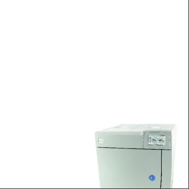
Autoclave - C17plus - Operating Instructions 3x2l5w
January 2022 0
Operating Instructions 3fy3y
March 2023 0
Panasonic Operating Instructions d5o6h
November 2019 72
Lr 1350 Operating Instructions 5k2ww
November 2019 118
Operating Instructions En 1t346
November 2019 64
u-95 Operating Instructions 1m438
November 2019 89More Documents from "mzst" 472b2z
Autoclave - C17plus - Operating Instructions 3x2l5w
January 2022 0
Smile Design Integrating Esthetics And Function Essentials In Esthetic Dentistry 1e-elsevier Mosby (2015) 1b3s3a
November 2021 0