Din En Iso 17640 E 2016-04 Principios Para Soldadura i1jc
This document was ed by and they confirmed that they have the permission to share it. If you are author or own the copyright of this book, please report to us by using this report form. Report 3i3n4
Overview 26281t
& View Din En Iso 17640 E 2016-04 Principios Para Soldadura as PDF for free.
More details 6y5l6z
- Words: 13,094
- Pages: 68
DEUTSCHE NORM
Entwurf
DIN EN ISO 17640 ICS 25.160.40
Entwurf
Einsprüche bis 2016-05-25 Vorgesehen als Ersatz für DIN EN ISO 17640:2011-04
Zerstörungsfreie Prüfung von Schweißverbindungen – Ultraschallprüfung – Techniken, Prüfklassen und Bewertung (ISO/DIS 17640:2016); Deutsche und Englische Fassung prEN ISO 17640:2016 Non-destructive testing of welds – Ultrasonic testing – Techniques, testing levels, and assessment (ISO/DIS 17640:2016); German and English version prEN ISO 17640:2016 Contrôle non destructif des assemblages soudés – Contrôle par ultrasons – Techniques, niveaux d’essai et évaluation (ISO/DIS 17640:2016); Version allemande et anglaise prEN ISO 17640:2016
Anwendungswarnvermerk Dieser Norm-Entwurf mit Erscheinungsdatum 2016-03-25 wird der Öffentlichkeit zur Prüfung und Stellungnahme vorgelegt. Weil die beabsichtigte Norm von der vorliegenden Fassung abweichen kann, ist die Anwendung dieses Entwurfes besonders zu vereinbaren. Stellungnahmen werden erbeten – vorzugsweise online im Norm-Entwurfs-Portal des DIN unter www.entwuerfe.din.de bzw. für Norm-Entwürfe der DKE auch im Norm-Entwurfs-Portal der DKE unter www.entwuerfe.normenbibliothek.de, sofern dort wiedergegeben; – oder als Datei per E-Mail an [email protected] möglichst in Form einer Tabelle. Die Vorlage dieser Tabelle kann im Internet unter www.din.de/stellungnahme oder für Stellungnahmen zu Norm-Entwürfen der DKE unter www.dke.de/stellungnahme abgerufen werden; – oder in Papierform an den DIN-Normenausschuss Materialprüfung (NMP), 10772 Berlin (Hausanschrift: Burggrafenstr. 6, 10787 Berlin). Die Empfänger dieses Norm-Entwurfs werden gebeten, mit ihren Kommentaren jegliche relevanten Patentrechte, die sie kennen, mitzuteilen und unterstützende Dokumentationen zur Verfügung zu stellen.
Gesamtumfang 68 Seiten
DIN-Normenausschuss Materialprüfung (NMP) DIN-Normenausschuss Schweißen und verwandte Verfahren (NAS)
Seite
Dieses Dokument (prEN ISO 17640:2016) wurde vom Technischen Komitee ISO/TC 44 „Welding and allied processes“ in Zusammenarbeit mit dem Technischen Komitee CEN/TC 121 „Schweißen und verwandte Verfahren“ erarbeitet, dessen Sekretariat vom DIN gehalten wird. Dieses Dokument ist derzeit zur parallelen Umfrage vorgelegt.
Der Text von ISO/DIS 17640:2016 wurde vom CEN als prEN ISO 17640:2016 ohne irgendeine Abänderung genehmigt.
ISO (die Internationale Organisation für Normung) ist eine weltweite Vereinigung von Nationalen Normungsorganisationen (ISO-Mitgliedsorganisationen). Die Erstellung von Internationalen Normen wird normalerweise von ISO Technischen Komitees durchgeführt. Jede Mitgliedsorganisation, die Interesse an einem Thema hat, für welches ein Technisches Komitee gegründet wurde, hat das Recht, in diesem Komitee vertreten zu sein. Internationale Organisationen, staatlich und nicht-staatlich, in Liaison mit ISO, nehmen ebenfalls an der Arbeit teil. ISO arbeitet eng mit der Internationalen Elektrotechnischen Kommission (IEC) bei allen elektrotechnischen Themen zusammen. Internationale Normen werden in Übereinstimmung mit den Gestaltungsregeln der ISO/IEC-Direktiven, Teil 2 erarbeitet. Die Hauptaufgabe von Technischen Komitees ist die Erarbeitung von Internationalen Normen. Der von dem Technischen Komitee angenommene Entwurf der Internationalen Norm wird zur Umfrage an die Mitgliedsorganisationen verteilt. Die Veröffentlichung einer Internationalen Norm benötigt eine Bestätigung von mindestens 75 % der abstimmenden Mitgliedsorganisationen Es wird auf die Möglichkeit hingewiesen, dass einige Elemente dieses Dokuments Patentrechte berühren können. ISO ist nicht dafür verantwortlich, einige oder alle diesbezüglichen Patentrechte zu identifizieren. Dieses Dokument (prEN ISO 17640:2016) wurde vom Technischen Komitee ISO/TC 44 „Welding and allied processes“ in Zusammenarbeit mit dem Technischen Komitee CEN/TC 121 „Schweißen und verwandte Verfahren“ erarbeitet in Übereinstimmung mit dem Abkommen über die technische Zusammenarbeit zwischen ISO und CEN (Wiener Vereinbarung), dessen Sekretariat vom DIN gehalten wird. Diese zweite Ausgabe ersetzt die erste Ausgabe (ISO 17640:2005), welche technisch überarbeitet wurde. Anfragen zur offiziellen Interpretation dieser Internationalen Norm jeglicher Art, sollten durch die nationalen Normungsinstitute an das Sekretariat von ISO/TC 44/SC 5 übermittelt werden. Eine vollständige Auflistung aller Normungsinstitute wird auf www.iso.org bereitgestellt.
Diese Internationale Norm legt Techniken zur manuellen Ultraschallprüfung von Schmelzschweißverbindungen in metallischen Werkstoffen mit Dicken gleich und größer als 8 mm fest, die bei Temperaturen des Prüfgegenstands von 0 °C bis 60 °C eine geringe Ultraschallschwächung zeigen (vor allem die durch Streuung verursachte). Sie gilt bevorzugt für Schweißverbindungen mit voll angeschlossenem Querschnitt, bei denen sowohl der Grundstoff als auch das Schweißgut ferritisch sind. Alle in dieser Internationalen Norm festgelegten werkstoffabhängigen Ultraschall-Größen beziehen sich auf Stähle mit den folgenden Schallgeschwindigkeiten: (5 920 50) m/s für Longitudinalwellen und (3 255 30) m/s für Transversalwellen. In dieser Internationalen Norm sind vier Prüfklassen festgelegt, die jeweils unterschiedlichen Wahrscheinlichkeiten für den Nachweis von Unregelmäßigkeiten entsprechen. Hilfestellung zur Wahl der Prüfklassen A, B und C wird im Anhang A gegeben. Diese Internationale Norm legt fest, dass die Anforderungen der Prüfklasse D, die für besondere Anwendungen vorgesehen ist, mit den allgemeinen Anforderungen übereinstimmen. Die Prüfklasse D kann nur dann angewendet werden, wenn dies in der Design-Spezifikation gefordert wird. Dies umfasst auch Prüfungen an anderen Metallen als ferritischer Stahl, Prüfungen an Schweißnähten mit unvollständiger Durchschweißung, Prüfungen mit automatisierten Vorrichtungen und Prüfungen bei Temperaturen des Prüfgegenstands außerhalb des Bereiches von 0 °C bis 60 °C. Diese Internationale Norm kann für die Bewertung von Anzeigen (zur Zulässigkeit) nach einer der folgenden Techniken angewendet werden: a)
die Bewertung basiert vorzugsweise auf der Länge und der Echohöhe der Anzeige;
b) die Bewertung basiert auf der Charakterisierung und der Größenabschätzung der Anzeigen mit Hilfe von Abtasttechniken. Diese Techniken müssen festgelegt werden.
Die folgenden Dokumente sind für die Anwendung dieses Dokuments erforderlich. Bei datierten Verweisungen gilt nur die in Bezug genommene Ausgabe. Bei undatierten Verweisungen gilt die letzte Ausgabe des in Bezug genommenen Dokuments (einschließlich aller Änderungen). ISO 5817, s ISO 9712, ISO 11666:2010, ISO 16810, ISO 16811, ISO 16826, ISO 17635,
s
ISO 23279, EN 1330-4, EN 12668 (alle Teile),
Für die Zwecke dieser Internationalen Norm gelten die Begriffe nach EN 1330-4 und ISO 17635. Für Formelzeichen, deren Definition und Einheiten, siehe Tabelle 1. Anzeigen sind nach ihrer Hauptrichtung in Bezug zur Schweißnahtachse x zu unterscheiden, entweder als Anzeigen in Längsrichtung oder als Anzeigen in Querrichtung, in Übereinstimmung mit Bild 2.
DDSR
Durchmesser des Kreisscheibenreflektors
mm
h
Ausdehnung der Anzeige in Tiefenrichtung
mm
l
Länge der Anzeige
mm
lx
In die x-Richtung projizierte Länge einer Anzeige
mm
ly
In die y-Richtung projizierte Länge einer Anzeige
mm
p
Ganzer Sprungabstand
mm
t
Dicke des Grundwerkstoffs *
mm
x
Position einer Inhomogenität in Längsrichtung
mm
y
Position einer Inhomogenität in Querrichtung
mm
z
Position einer Inhomogenität in Tiefenrichtung
mm
* Falls die verschweißten Teile nicht die gleichen Dicken aufweisen, muss die kleinste Dicke berücksichtigt werden.
Zweck dieser Internationalen Norm ist es, allgemeine Techniken der Ultraschallprüfung für übliche Schweißverbindungen und für Temperaturen der Prüfgegenstände zwischen 0 °C und 60 °C nach einheitlichen Gesichtspunkten zu beschreiben. Die spezifischen Festlegungen in dieser Internationalen Norm betreffen die Kriterien, die Prüfvorbereitung, die Durchführung der Prüfung und den Prüfbericht. Die festgelegten Kenngrößen, besonders die für Prüfköpfe, sind vereinbar mit den Anforderungen von ISO 11666 und ISO 23279.
Diese beinhalten: a)
Methode zur Einstellung der Bezugshöhe;
b) zur Bewertung der Anzeigen anzuwendende Methode; c)
Zulässigkeitsgrenzen;
d) Prüfklasse; e)
Phase(n) bei der Herstellung und Bearbeitung, in der/denen die Prüfung durchzuführen ist;
f)
Qualifikation des Prüfpersonals;
g)
Prüfumfang für Anzeigen in Querrichtung;
h) Anforderungen an eine zusätzliche Tandemprüfung (siehe ISO 16826); i)
Prüfung des Grundwerkstoffs vor und/oder nach dem Schweißen;
j)
einen Hinweis darauf, ob eine schriftliche Prüfanweisung erforderlich ist;
k) Anforderungen an eine schriftliche Prüfanweisung.
Bevor jede Prüfung einer Schweißverbindung beginnen kann, müssen dem Prüfer folgende wichtige Informationen zugänglich sein: a)
schriftliche Prüfanweisung, falls gefordert (siehe 5.3);
b) Art(en) des Grundwerkstoffs und der Produktform (z. B. gegossen, geschmiedet, gewalzt); c)
Phase der Herstellung oder der Bearbeitung, in der die Prüfung durchzuführen ist, einschließlich der Wärmebehandlung, sofern eine solche durchgeführt wird;
d) Zeitpunkt und Umfang jeder Wärmebehandlungen nach dem Schweißen; e)
Nahtvorbereitung und Nahtabmessungen;
f)
Anforderungen an den Oberflächenzustand;
g)
Schweißausführung oder wichtige Informationen zum Schweißprozess;
h) Anforderungen an den zu Prüfbericht; i)
Zulässigkeitsgrenzen;
j)
Umfang der Prüfung einschließlich der Anforderungen für Anzeigen in Querrichtung, wenn zutreffend;
k) Prüfklasse; l)
Qualifikationsstufe des Prüfpersonals;
m) Vorgehensweise bei Korrekturmaßnahmen, wenn unzulässige Anzeigen festgestellt werden.
Üblicherweise erfüllen die Festlegungen dieser Internationalen Norm die Forderungen nach einem schriftlichen Prüfanweisungen. Wo das nicht der Fall ist, oder wenn die in dieser Norm aufgeführten Prüftechniken für die zu prüfende Schweißverbindung nicht anwendbar sind, müssen zusätzliche schriftliche Prüfverfahren verwendet werden, sofern dies durch die Design-Spezifikation gefordert wird.
Das Personal, das Prüfungen nach dieser Internationalen Norm durchführt, muss auf einer angemessenen Stufe der Ultraschallprüfung nach ISO 9712 oder einer gleichwertigen Norm für den jeweiligen Industriesektor qualifiziert sein. Zusätzlich zum allgemeinen Wissen über die Schweißnahtprüfung mit Ultraschall muss das Personal auch mit den besonderen Prüfproblemen vertraut sein, die mit der Art der zu untersuchenden Schweißverbindung zusammenhängen.
Jede Prüfausrüstung, die im Zusammenhang mit dieser Internationalen Norm genutzt wird, muss die Anforderungen nach EN 12668 (alle Teile) erfüllen.
Die Prüffrequenz muss im Bereich von 1,5 MHz bis 5 MHz liegen und so ausgewählt werden, dass sie zu den festgelegten Zulässigkeitsgrenzen t. Bei der erstmaligen Prüfung muss die Frequenz innerhalb des oben angegebenen Bereiches so niedrig wie möglich sein, wenn die Auswertung nach Zulässigkeitsgrenzen durchgeführt wird, die auf der Länge und der Amplitude der Anzeigen basieren, wie z. B. ISO 11666. Höhere Prüffrequenzen dürfen bei Bedarf zur Verbesserung der Auflösung benutzt werden, wenn Normen herangezogen werden, bei denen die Zulässigkeitsgrenzen auf der Charakterisierung von Unregelmäßigkeiten beruhen, wie z. B. ISO 23279. Prüffrequenzen von etwa 1 MHz dürfen bei Prüfungen mit langen Schallwegen verwendet werden, wenn der Werkstoff eine überdurchschnittliche Schallschwächung zeigt.
Bei einer Prüfung mit Transversalwellen und Prüftechniken, bei denen eine Reflexion des Schallbündels von der gegenüberliegenden Oberfläche gefordert wird, muss sichergestellt sein, dass der Auftreffwinkel des Schallbündels auf die gegenüberliegende Oberfläche zwischen 35° und 70° liegt. In Fällen, in denen mehrere Einschallwinkel verwendet werden, muss mindestens einer der verwendeten Winkelprüfköpfe diese Anforderung erfüllen. Weiterhin muss einer der verwendeten Einschallwinkel sicherstellen, dass die Schweißnahtflanken so gut wie möglich senkrecht getroffen werden. Falls die Verwendung von zwei oder mehr Einschallwinkel gefordert wird, muss der Unterschied zwischen den Nennwerten der Einschallwinkel 10° oder mehr betragen. Im Falle gekrümmter Prüfoberfläche dürfen die Auftreffwinkel an der Prüffläche und an der gegenüber liegenden reflektierenden Fläche mit Hilfe einer Querschnittszeichnung der Schweißnaht oder mit den in ISO 16811 beschriebenen Techniken bestimmt werden. Können die Auftreffwinkel nicht nach dieser Internationalen Norm bestimmt werden, muss der Prüfbericht eine zusammenfassende Darstellung der verwendeten Einschallrichtungen, der Ausdehnung der ungeprüften Bereiche und eine Erläuterung der aufgetretenen Schwierigkeiten enthalten.
Die Wandlergröße muss in Abhängigkeit vom auftretenden Ultraschallweg und von der Prüffrequenz ausgewählt werden. Je kleiner der Wandler ist, umso kleiner sind die Länge und Breite des Nahfeldes, und umso größer ist die Öffnung des Schallbündels im Fernfeld bei der vorgegebenen Frequenz. Kleine Prüfköpfe mit Wandlern, deren Durchmesser zwischen 6 mm und 12 mm beträgt (oder mit rechteckigen Schwingern mit einer gleichen Fläche) sind daher am günstigsten, wenn mit kurzen Schallwegen gearbeitet wird. Für Bereiche mit längeren Schallwegen, d. h. länger als 100 mm für Einschinger-Senkrechtprüfköpfe und länger als 200 mm für Winkelprüfköpfen ist eine Wandlergröße von 12 mm bis 24 mm besser geeignet.
Der Spalt g zwischen Prüffläche und Sohle des Prüfkopfschuhs darf nicht mehr als 0,5 mm betragen. Für zylindrische oder kugelige Oberflächen kann diese Forderung mit Hilfe von Gleichung (1) geprüft werden: (1) Dabei ist a
die Länge des Prüfkopfschuhs in Prüfrichtung, in Millimeter;
D
der Durchmesser des Bauteils, in Millimeter.
Resultiert aus der Gleichung ein Wert für g, der größer als 0,5 mm ist, muss der Prüfkopfschuh an die Oberfläche anget und eine entsprechende Empfindlichkeits- und Prüfbereichseinstellung durchgeführt werden.
Die Koppelmittel müssen in Übereinstimmung mit ISO 16810 sein. Für die Empfindlichkeits- und die Prüfbereichseinstellung sowie für die Prüfung muss dasselbe Koppelmittel verwendet werden.
Das Prüfvolumen (siehe Bild 1) wird als die Zone festgelegt, die Schweißnaht und Grundwerkstoff auf beiden Seiten der Schweißnaht über eine Breite von mindestens 10 mm umfasst, oder als die Zone, die der Breite der Wärmeeinflusszone entspricht, wobei jeweils der größere Wert gilt. In jedem Fall muss bei der Prüfung das gesamte Prüfvolumen erfasst werden. Wenn einzelne Bereiche des Prüfvolumens in mindestens einer Prüfrichtung nicht erfasst werden können, oder wenn die Auftreffwinkel an der Gegenfläche nicht die Anforderungen von 6.3.2 erfüllen, müssen andere oder zusätzliche Ultraschalltechniken oder andere zerstörungsfreie Prüfverfahren vereinbart werden. Dies kann in einigen Fällen das Entfernen der Schweißnahtüberhöhung erfordern. Zusätzliche Techniken können die Prüfung mit SE-Winkelprüfköpfen, Kriechwellenprüfköpfen, weitere Ultraschalltechniken oder andere geeignete Verfahren erfordern, z. B. die Eindringprüfung, die Magnetpulverprüfung, die Durchstrahlungsprüfung. Bei der Auswahl alternativer oder zusätzlicher Methoden sollten die Art der Schweißverbindung und die wahrscheinliche Orientierung der nachzuweisenden Unregelmäßigkeiten besonders beachtet werden.
Die Prüfflächen müssen groß genug sein, um das Prüfvolumen (siehe Bild 1) vollständig erfassen zu können. Alternativ darf die Breite der Abtastflächen verkleinert werden, wenn eine gleichwertige Überdeckung des Prüfvolumens durch Abtastung sowohl von der oberen als auch von der unteren Nahtseite aus erreicht werden kann. Die Prüfflächen müssen eben und frei von ankopplungsstörenden Verunreinigungen sein (z. B. von Rost, losem Zunder, Schweißspritzern, Kerben und Riefen). Die Welligkeit der Prüffläche darf nicht zu einem Spalt zwischen Prüfkopf und Prüffläche führen, der größer als 0,5 mm ist. Zur Erfüllung dieser Anforderungen sind die Prüfflächen gegebenenfalls zu bearbeiten. Lokale Unregelmäßigkeiten im Oberflächenverlauf, z. B. entlang des Schweißnahtrandes, die unter dem Prüfkopf zu einem Spalt bis zu 1 mm führen können, sind nur dann zulässig, wenn von dieser Seite aus mit mindestens einem zusätzlichen Einschallwinkel geprüft wird. Diese zusätzliche Prüfung ist notwendig, um die Einschränkung des Prüfvolumens auszugleichen, die bei einem Spalt dieser Größenordnung auftritt. Die Prüfflächen sowie die Oberflächen, an denen das Schallbündel reflektiert wird, müssen eine ungestörte Ankopplung und Reflexion erlauben.
Der Grundwerkstoff muss im Bereich der Prüffläche (siehe Bild 1) vor oder nach dem Schweißen mit Senkrechtprüfköpfen geprüft werden; auf diese Prüfung darf verzichtet werden, wenn (z. B. durch frühere Prüfungen während des Fertigungsprozesses) nachgewiesen werden kann, dass die Prüfung der Schweißverbindung mit Winkelprüfköpfen durch die Unregelmäßigkeiten oder durch hohe Schallschwächung nicht behindert wird. Wenn Unregelmäßigkeiten gefunden werden, muss ihr Einfluss auf die vorgesehene Prüfung mit Winkelprüfköpfen abgeschätzt werden, und wenn notwendig müssen die Prüftechniken entsprechend anget werden. Wenn eine zufrieden stellende Erfassung des Prüfvolumens durch eine Ultraschallprüfung ernsthaft beeinträchtigt ist, müssen andere Prüfverfahren (z. B. eine Durchstrahlungsprüfung) erwägt werden.
Maße in Millimeter
1 2 3
Position 1 Position 2 Position 3
a b
Breite des Prüfvolumens Breite der Prüffläche
Die Prüfbereichs- und Prüfempfindlichkeitseinstellungen müssen vor jeder Prüfung nach dieser Internationalen Norm und nach ISO 16811 durchgeführt werden und sie müssen die Temperatur berücksichtigen. Die Temperaturdifferenz bei der Prüfbereichs- und Empfindlichkeitseinstellung und während der Prüfung muss innerhalb 15 °C liegen. Diese Einstellungen müssen mindestens alle 4 h und nach Ende der Prüfung überprüft werden. Überprüfungen müssen auch durchgeführt werden, wenn Systemeinstellungen verändert oder wenn Veränderungen der Einstellungen vermutet werden. Falls während dieser Überprüfungen Abweichungen größer als 2 dB bzw. 1 % der Spannweite festgestellt werden, müssen die in der Tabelle 2 angegebenen Korrekturen durchgeführt werden.
1
Abweichungen
4 dB
Die Geräteeinstellung muss korrigiert werden bevor weiter geprüft wird.
2
Reduzierung der Empfindlichkeit 4 dB
Die Geräteeinstellung muss korrigiert werden und alle in dem vorherigen Zeitraum durchgeführten Prüfungen mit der Ausrüstung müssen wiederholt werden.
3
Erhöhung der Empfindlichkeit 4 dB
Die Geräteeinstellung muss korrigiert werden und alle registrierten Anzeigen müssen neu bewertet werden.
1
Abweichungen Prüfbereichs
2 % des
Die Geräteeinstellung muss korrigiert werden bevor weiter geprüft wird.
2
Abweichungen 2 % des Prüfbereichs
Die Geräteeinstellung muss korrigiert werden und alle in dem vorherigen Zeitraum durchgeführten Prüfungen mit der Ausrüstung müssen wiederholt werden.
Eine der folgenden Techniken zum Einstellen der Bezugsempfindlichkeit muss verwendet werden. Die Verwendung dieser Techniken kann zu unterschiedlichen Prüfergebnissen führen. Unterschiedliche Prüfergebnisse können durch die Verwendung unterschiedlicher Techniken für die Empfindlichkeitseinstellung entstehen. a)
Technik 1: als Bezugsgröße dient eine Abstands-Amplituden-Kurve (DAC-Kurve; en: distanceamplitude curve) für Querbohrungen von 3 mm Durchmesser;
b) Technik 2: die Bezugsgrößen für Transversal- und Longitudinalwellen bei Anwendung der AbstandVerstärkungsgröße-Methode (AVG-Methode) für Kreisscheibenreflektor (KSR) sind in den Tabellen 3 bzw. 4 angegeben; c)
Technik 3: als Bezugsgröße dient eine rechteckige Nut mit 1 mm Tiefe und 1 mm Breite. Diese Technik kann nur im Dickenbereich 8 mm t 15 mm und nur für Einschallwinkel 70° verwendet werden;
d) Technik 4: als Bezugsgröße für die Tandemprüfung dient ein rechtwinklig zur Prüffläche liegendes Flachbodenloch mit 6 mm Durchmesser (für alle Wanddicken). Diese Technik ist nur für Einschallwinkel von 45° im Dickenbereich t mm anwendbar. Die Länge der Querbohrungen und Nuten muss größer sein als die bei !20 dB gemessene Breite des Schallbündels.
t 8 mm MHz 1,5 bis 2,5 3,0 bis 5,0
t 15 mm
AL 2
AL 3
—
—
DDSR = 1,5 mm
DDSR = 1,5 mm
15 mm AL 2
t 40 mm
40 mm
AL 3
t 100 mm
AL 2
AL 3
DDSR = 2,5 mm
DDSR = 2,5 mm
DDSR = 3,0 mm
DDSR = 3,0 mm
DDSR = 2,0 mm
DDSR = 2,0 mm
DDSR = 3,0 mm
DDSR = 3,0 mm
DDSR ist der Durchmesser des Kreisscheibenreflektors.
t 8 mm MHz 1,5 bis 2,5 3,0 bis 5,0
t 15 mm
AL 2
AL 3
—
—
DDSR = 2,0 mm
DDSR = 2,0 mm
15 mm AL 2
t 40 mm
40 mm
AL 3
t 100 mm
AL 2
AL 3
DDSR = 2,5 mm
DDSR = 2,5 mm
DDSR = 3,0 mm
DDSR = 3,0 mm
DDSR = 2,0 mm
DDSR = 2,0 mm
DDSR = 3,0 mm
DDSR = 3,0 mm
DDSR ist der Durchmesser des Kreisscheibenreflektors.
Alle Anzeigen, die die folgenden Grenzwerte erreichen oder überschreiten, müssen bewertet werden. Die Bewertungsschwellen für die Techniken 1 bis 4 sind in ISO 11666:20xx, Tabelle A.1 angegeben.
Werden zur Festlegung der Bezugsschwellen getrennte Blöcke verwendet, müssen an einer repräsentativen Anzahl von Orten Messungen der Unterschiede der Schallübertragung zwischen Prüfgegenstand und Bezugskörper durchgeführt werden. Geeignete Techniken dazu sind in ISO 16811 beschrieben. Wenn diese Unterschiede kleiner als 2 dB sind, ist keine Korrektur gefordert. Wenn die Unterschiede größer als 2 dB, aber kleiner als 12 dB sind, ist eine Korrektur notwendig. Wenn die Transferverluste 12 dB überschreiten, muss der Grund dafür ermittelt und die Prüfflächen gegebenenfalls erneut überarbeitet werden. Falls es keine nahe liegenden Erklärungen für die hohen Korrekturwerte gibt, muss die Schallschwächung an verschiedenen Stellen des Prüfgegenstandes bestimmt werden, und wo es starke Abweichungen gibt müssen Korrekturmaßnahmen erwogen werden.
Während der Schweißnahtprüfung muss der Störpegel mindestens 12 dB unter der Bewertungsschwelle liegen; ausgenommen sind dabei vereinzelte Anzeigen von der Oberfläche. Diese Forderung darf gelockert werden, wenn es in der Design-Spezifikation vorgesehen ist.
Die Qualitätsanforderungen an Schweißverbindungen richten sich vor allem nach den verwendeten Werkstoffen, dem Schweißprozess und den Betriebsbedingungen. Um allen Anforderungen gerecht zu werden, legt diese Internationale Norm vier Prüfklassen fest (A, B, C und D). Von der Prüfklasse A hin zur Prüfklasse C wird eine erhöhte Auffindwahrscheinlichkeit erreicht durch eine erhöhte Prüfüberdeckung, z. B. durch eine höhere Anzahl von Einschallungen, durch eine Oberflächenbearbeitung. Die Prüfklasse D darf unter Anwendung einer schriftlichen Prüfanweisung für besondere Anwendungen vereinbart werden, wobei die allgemeinen Anforderungen dieser Internationalen Norm berücksichtigt werden müssen. Die Prüfklassen beziehen sich allgemein auf die Bewertungsgruppen (z. B. nach ISO 5817). Eine angemessene Prüfklasse kann in Schweißnaht-Prüfnormen (z. B. nach ISO 17635), Produktnormen oder anderen Dokumenten angegeben sein. Bei der Anwendung von ISO 17635 werden die in Tabelle 5 angegebenen Prüfklassen empfohlen.
A
C, D
B
B
C
zu vereinbaren
D
besondere Anwendung
Die besonderen Anforderungen an die Prüfklassen A bis C sind für verschiedene Verbindungsarten im Anhang A aufgeführt. Die dargestellten Verbindungsarten stellen den Idealfall dar. Wenn die tatsächlichen Schweißbedingungen oder die Zugänglichkeit nicht genau mit diesen übereinstimmen, muss die Prüftechnik geändert werden, um sowohl die allgemeinen Anforderungen dieser Internationalen Norm als auch die der geforderten Prüfklasse zu erfüllen. In diesen Fällen muss eine schriftliche Prüfanweisung erstellt werden.
Die Ultraschallprüfungen müssen nach ISO 16810 und den zusätzlichen Festlegungen in 12.2 bis 12.5 durchgeführt werden.
Während der Schrägeinschallung (wie in Bild 1 dargestellt) muss der Prüfkopf, bezogen auf die nominelle Einschallrichtung, bis zu einem Winkel von etwa 10° leicht nach links und rechts geschwenkt werden.
Innenliegende flächige Unregelmäßigkeiten mit einer Orientierung senkrecht zur Prüffläche sind mit der Schrägeinschallung mit Einzelschwingerprüfköpfen schwer nachzuweisen. Für solche Unregelmäßigkeiten sollten spezielle Prüftechniken ausgewählt werden, besonders für Schweißnähte in dickwandigeren Werkstoffen. Die Anwendung dieser Prüftechniken muss durch die Design-Spezifikation festgelegt werden.
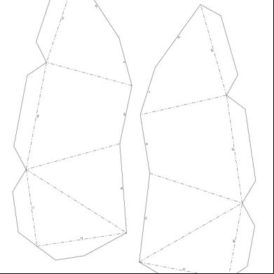
Die Position aller Inhomogenitäten muss in Bezug zu einem Koordinatensystem festgelegt werden, z. B. wie in Bild 2 dargestellt. Ein Punkt auf der Prüffläche muss als Bezugspunkt für die Messungen festgelegt werden. Wird die Prüfung von mehr als einer Oberfläche aus durchgeführt, muss auf jeder dieser Oberflächen ein Bezugspunkt festgelegt werden. In diesem Fall muss darauf geachtet werden, dass eine räumliche Beziehung zwischen allen verwendeten Bezugspunkten hergestellt wird, so dass die absolute Position aller Inhomogenitäten von jedem dieser Bezugspunkte aus bestimmt werden kann. Bei Umfangsnähten kann diese Forderung die Festlegung von inneren und äußeren Bezugspunkten vor dem Schweißen erforderlich machen.
O
Bezugspunkt
ANMERKUNG Bezüglich der Definition von h, l, lx , ly , x, y, z siehe Tabelle 1.
Alle relevanten Anzeigen über der Beobachtungsschwelle müssen nach den Festlegungen in 12.5.2 bis 12.5.4 bewertet werden.
Die Echohöhe muss durch Prüfkopfbewegung maximiert werden und bezogen auf die Bezugsschwelle aufgezeichnet werden.
Die Länge einer Anzeige in Längs- oder in Querrichtung (lx, ly), muss, falls möglich und nicht anders vereinbart, mit der in der Norm für Zulässigkeitsgrenzen festgelegten Technik bestimmt werden.
Die Anzeige der Höhenmessung darf nur dann durchgeführt werden, wenn dies in der Design-Spezifikation gefordert wird.
Wenn es in der Design-Spezifikation festgelegt ist, müssen Inhomogenitäten nach ISO 23279 charakterisiert werden.
Der Prüfbericht muss mindestens die folgenden Angaben umfassen: a)
Beschreibung des Prüfgegenstandes: 1) Werkstoff und Produktform; 2) Maße; 3) Position der geprüften Schweißnaht, Skizze zur geometrischen Konfiguration (falls nötig); 4) Hinweis auf das Schweißverfahren, die Design-Spezifikation und die Wärmebehandlung; 5) Fertigungszustand; 6) Oberflächenbeschaffenheit; 7) Temperatur des Prüfgegenstandes;
b) vertragliche Anforderungen, z. B. Design-Spezifikationen, Richtlinien, besondere Vereinbarungen usw.; c)
Ort und Datum der Prüfung;
d) Name der prüfenden Stelle, Name und Qualifizierung des Prüfers; e)
Hersteller und Typ des verwendeten Ultraschallgerätes mit Identnummer, falls gefordert;
f)
Hersteller, Typ, Nennfrequenz, Wandlergröße und tatsächlicher Einschallwinkel der genutzten Prüfköpfe, mit Identnummer des Prüfkopfs, falls gefordert;
g)
Angaben zu den verwendeten Vergleichskörpern mit Skizzen, falls nötig;
h) Koppelmittel; i)
Prüfklasse(n) und Hinweis auf eine Prüfanweisung, falls angewendet;
j)
Prüfumfang;
k) Lage der Prüfflächen; l)
Bezugspunkte und Angaben zu dem verwendeten Koordinatensystem, wie in 12.4 angegeben;
m) Kennzeichnung der Prüfkopfstellungen, entweder nach Anhang A oder durch eine Skizze; n) Prüfbereich; o) Verfahren und Zahlenwerte der Empfindlichkeitseinstellung (Einstellung der Bezugsschwellen und der für Transferkorrekturen verwendeten Werte); p) Bezugsschwellen; q) Ergebnis der Prüfung des Grundwerkstoffes; r)
Normen für die Zulässigkeitsgrenzen;
s)
Abweichungen von dieser Internationalen Norm oder von den getroffenen vertraglichen Vereinbarungen.
t)
Koordinaten der Inhomogenitäten, wie in 12.4 festgelegt, mit detaillierten Angaben zu den verwendeten Prüfköpfen und den zugehörigen Prüfkopfpositionen;
u) maximale Echohöhen, wie in 12.5.2 festgelegt, sowie Informationen über die Art und die Abmessung der Inhomogenitäten, falls erforderlich; v)
Längen der Anzeigen, wie in 12.5.3 festgelegt;
w) Ergebnis der Bewertung in Bezug auf die festgelegten Zulässigkeitsgrenzen; x)
eine Verweisung auf diese Internationale Norm (ISO 17640:20xx).
(normativ)
Siehe Bilder A.1 bis A.7 und Tabellen A.1 bis A.7
1
Seite 1
2
Draufsicht
3
Seite 2
4
Seitenansicht
A, B, C, D, E, F, G, H, W, X, Y, Z
Prüfkopfpositionen
b
Prüfflächenbreite (SZW; en: scanning zone width) in Bezug zum Sprungabstand p ganzer Sprungabstand
p
(Symbole siehe Legende Bild A.1)
mm 8
t 15
1
A oder B
1,25 p
—
2
a
1
(X und Y) oder (W und Z)
4
c
15
t 40
1
A oder B
1,25 p
—
2
a
1
(X und Y) oder (W und Z)
4
c
8
t 15
1
A oder B
1,25 p
—
2
e
1
(X und Y) oder (W und Z)
4
c
15
t 40
2f
A oder B
1,25 p
—
4
be
1
(X und Y) oder (W und Z)
4
c
40
t 60
2
A oder B
1,25 p
—
4
b
2
(X und Y) oder (W und Z)
8
c
2
A oder B
1,25 p
—
4
b
2
(C und D) oder (E und F)
4
cd
1
A oder B
1,25 p
G oder H
3
d
1
(C und D) oder (E und F)
2
d
2
A oder B
1,25 p
G oder H
5
bd
2
(C und D) oder (E und F)
4
d
2
A oder B
1,25 p
G oder H
5
bd
2
(C und D) oder (E und F)
4
d
A
B
60
8
C
15
100
t
t 15
t
40
! 40 a
Darf nach Vereinbarung auf eine Abstastung von einer Seite aus reduziert werden.
b
Zusätzliche Prüfung mit der Tandemtechnik nach besonderer Vereinbarung.
c
Nur bei besonderer Vereinbarung gefordert.
d
Die Beschaffenheit der Nahtüberhöhung muss mit den Anforderungen aus Abschnitt 8 übereinstimmen. Dies kann das Beschleifen der Naht erforderlich machen. Jedoch kann im Falle von einseitigen Rohrumfangsnähten nur die äußere Decklage beschliffen werden.
e
Falls nur von einer Seite zugänglich, müssen zwei Einschallwinkel verwendet werden.
f
Im Dickenbereich von 15 mm t 25 mm ist ein Einschallwinkel ausreichend, vorausgesetzt die Frequenz ist kleiner als 3 MHz.
ANMERKUNG
L-Abtastung: N-Abtastung: T-Abtastung: p
Prüfung auf Anzeigen in Längsrichtung mit Winkelprüfköpfen; Prüfung mit Senkrechtprüfköpfen; Prüfung auf Anzeigen in Querrichtung mit Winkelprüfköpfen; ist der ganze Sprungabstand.
a) Schnittbild
1 2 A, B, C, D, E, F, G, W, X, Y, Z a, b, c, d, e, f, g t
Teil 1 Teil 2 Prüfkopfpositionen Breitenangaben für die Prüfflächen Dicke
b) Seitenansicht
(Symbole siehe Legende Bild A.2)
mm 8
t 15
1
A oder B
1,25 p
Cc
—
1
—
—
—
—
a
15
t 40
1
A oder B
1,25 p
Cc
c
2
—
—
—
—
a
8
t 15
1
A oder B
1,25 p
Cc
—
2
1
F und G
c
2
b
15
t 40
1
A und B
1,25 p
Cc
c
3
1
(F und G) oder (X und Y) oder (W und Z)
f+g
2
b
2
A und B
0,75 p
Cc
c
5
1
(F und G) oder (X und Y) oder (W und Z)
f+g
2
b
1
A und B
1,25 p
Cc
c
3
2
F und G
4
b
2
(A und B) und (D und E)
1,25 p
Cc
c
7
1
(F und G) und (X und Y) oder (W und Z)
f+g
4
b
(A und B) und (D und E)
0,75 p
Cc
c
7
2
(F und G) und (X und Y) oder (W und Z)
f+g
8
b
(A und B) und (D und E)
0,75 p
Cc
c
9
2
(F und G) und (X und Y) oder (W und Z)
f+g
8
b
A
B 40
t
100
8
t 15
15
t 40
1
d+e
C 40
t
100
! 100
2 1 3 1
d+e
d+e
a Nicht anwendbar. b Darf nur nach besonderer Vereinbarung durchgeführt werden. c Ist durch die Tandemtechnik von A oder B aus zu ersetzen, wenn Position C nicht möglich ist.
ANMERKUNG
L-Abtastung: N-Abtastung: T-Abtastung: p
Prüfung auf Anzeigen in Längsrichtung mit Winkelprüfköpfen; Prüfung mit Senkrechtprüfköpfen; Prüfung auf Anzeigen in Querrichtung mit Winkelprüfköpfen; ist der ganze Sprungabstand.
c
c
c f+g c
c
c
a) Querschnittsfläche
b) Draufsicht
1
Teil 1: Zylindrische Behälterwand/ebenes Blech
2
Teil 2: Stutzen
3
Senkrechtprüfkopf
A, B, C, D, E, F, U, V, W, X, Y, Z
Prüfkopfpositionen
a, b, c, d, e
Breitenangaben für die Prüfflächen Dicke
t
(Symbole siehe Legende Bild A.3)
mm 8
t 15
1
A
1,25 p
C
c
1
—
—
—
a
15
t 40
1
A oder F oder D
1,25 p d
C
c
2
—
—
—
a
8
t 15
1
A oder D
C
c
2
1
(U und V) oder (X und Y) oder (W und Z)
2
b
15
t 40
1
A oder (D und E)
1,25 p
C
c
2 oder 3
1
(U und V) oder (X und Y) oder (W und Z)
2
b
40
t 60
1
(A oder B) und (D und E)
1,25 p
C
c
4
1
(X und Y) und (W und Z)
4
b
(A und B) und (D und E)
0,5 p
C
c
7
2
(X und Y) und (W und Z)
8
b
C
c
3
1
(U und V) oder (X und Y) und (W und Z)
2 oder 4
b
C
c
5
2
(X und Y) und (W und Z)
8
b
C
c
9
2
(X und Y) und (W und Z)
8
b
A
1,25 p d+e
d+e
B
60
8
15
C
t
100
t 15
t
40
! 40
2 1
d+e
d+e 1,25 p
1
(A oder B) und (D oder E)
d oder e
2
(A oder B) und (D oder E)
d oder e
2
(A oder B) und (D oder E)
0,5 p
0,5 p d+e
a Nicht anwendbar. b Darf nur nach besonderer Vereinbarung durchgeführt werden. ANMERKUNG
L-Abtastung: N-Abtastung: T-Abtastung: p
Prüfung auf Anzeigen in Längsrichtung mit Winkelprüfköpfen; Prüfung mit Senkrechtprüfköpfen; Prüfung auf Anzeigen in Querrichtung mit Winkelprüfköpfen; ist der ganze Sprungabstand.
a) Querschnittsfläche
1
Teil 1: Stutzen
2
Teil 2: Behälterwand
A, B, C, D, E, F, G, H, X, Y
Prüfkopfpositionen
a, b, c
Prüfflächenbreiten Dicke
t
b) Schnittbild
(Symbole siehe Legende Bild A.4)
mm 8
t 15
1
A oder B oder H
1,25 p
C
c
1
—
—
—
a
1
A oder B oder H
1,25 p
C
c
2
—
—
—
a
A 15
B
40
t
8
t 15
1
A oder B oder H
1,25 p
C
c
1
1
(F und G) oder (X und Y)
2
b
15
t 40
2
A oder B oder H
1,25 p
C
c
3
2
(F und G) oder (X und Y)
4
b
2
(H oder A) und B
0,75 p
C
c
5
2
D und E
4
bc
40
t
100
8
t 15
1
(H oder A) und B
1,25 p
C
c
3
1
D und E
2
bc
15
t 40
2
(H oder A) und B
1,25 p
C
c
5
1
D und E
2
bc
3
(H oder A) und B
1,25 p
C
c
7
2
D und E
4
bc
3
(H oder A) und B
0,5 p
C
c
7
2
D und E
4
bc
C 40
t
100
! 100 a
Nicht anwendbar.
b
Darf nur nach besonderer Vereinbarung durchgeführt werden.
c
Die Beschaffenheit der Nahtüberhöhung muss mit den Anforderungen aus Abschnitt 8 übereinstimmen. Dies kann das Beschleifen der Naht erforderlich machen.
ANMERKUNG L-Abtastung:
Prüfung auf Anzeigen in Längsrichtung mit Winkelprüfköpfen;
N-Abtastung:
Prüfung mit Senkrechtprüfköpfen;
T-Abtastung:
Prüfung auf Anzeigen in Querrichtung mit Winkelprüfköpfen;
p
ist der ganze Sprungabstand.
a) Querschnittsfläche
1
Teil 1: Stutzen
2
Teil 2: Behälterwand
3
Senkrechtprüfkopf
A, B, C, D, X, Y
Prüfkopfpositionen
a, b, c, d, x
Prüfflächenbreiten Dicke
t
b) Draufsicht
(Symbole siehe Legende Bild A.5)
mm 8
t 15
1
A oder B
1
A oder B
A 15
t
40
8
t 15
2
A oder B
15
t 40
2
A oder B
40
t 60
2
A und (B oder D)
2
A und (B oder D)
1,25 p 0,50 p 1,25 p 0,50 p 1,25 p 0,50 p 1,25 p 0,50 p
—
—
1
—
—
—
a
C
c
2
—
—
—
a
—
—
2
1
X und Y
2
bc
C
c
3
1
X und Y
2
bc
C
c
5
2
X und Y
4
bc
C
c
5
2
X und Y
4
bc
C
c
4
1
X und Y
2
bc
C
c
4
1
X und Y
2
bc
C
c
7
2
X und Y
4
bc
C
c
7
2
X und Y
4
bc
B
60
t
100
8
t 15
3
A oder B
15
t 40
3
A oder B
40
t 60
3
A und B
3
A und B
C
60
t
100
1,25 p 0,50 p 1,25 p 0,5 p 1,25 p 0,5 p 1,25 p 0,5 p 1,25 p 0,5 p 1,25 p 0,5 p
a
Nicht anwendbar.
b
Darf nur nach besonderer Vereinbarung durchgeführt werden.
c
Die Beschaffenheit der Decklage muss mit den Anforderungen aus Abschnitt 8 übereinstimmen. Dies kann das Beschleifen der Decklage erforderlich machen.
ANMERKUNG L-Abtastung: N-Abtastung: T-Abtastung: p
Prüfung auf Anzeigen in Längsrichtung mit Winkelprüfköpfen; Prüfung mit Senkrechtprüfköpfen; Prüfung auf Anzeigen in Querrichtung mit Winkelprüfköpfen; ist der ganze Sprungabstand.
a) Schnittbild
b) Seitenansicht
1
Teil 1
2
Teil 2
3
Teil 3
A, B, C, D, E, F, G, H, W, W1, W2, X, X1, X2, Y, Y1, Y2, Z, Z1, Z2
Prüfkopfpositionen
a, b, c, d, e, f, g, h
Prüfflächenbreiten Dicke
t
(Symbole siehe Legende Bild A.6)
mm 1
(A und C) oder (B und D)
1,25 p
2
—
—
—
—
a
1
A und B und C und D
0,75 p
4
c
—
—
—
a
2
A und B und C und D
0,75 p
8
c
—
—
—
—
8 !t! 15
1
A und B und C und D
1,25 p
4
—
1
(X1 und Y1 und W1 und Z1) und (X2 und Y2 und W2 und Z2)
8
b
15 t
2
A und B und C und D
0,75 p
8
c
1
(X1 und Y1 und W1 und Z1) und (X2 und Y2 und W2 und Z2)
8
b
2
(A und B und C und D) und (E und F und G und H)
0,75 p
2
(X1 und Y1 und W1 und Z1) und (X2 und Y2 und W2 und Z2)
16
b
2
(X1 und Y1 und W1 und Z1) und (X2 und Y2 und W2 und Z2)
16
b
8 A
15 !t 40 40
B
t 15
t
100
40
40 !t !100
C
40
t !100!
1
2 1
(A und B) und (C und D) und (E und F) und (G und H)
und Tandem (A und B) und (C und D)
12
e!h
0,75 p e!h
14
d d
—
a
Nicht anwendbar.
b
Darf nur nach besonderer Vereinbarung durchgeführt werden.
c
Falls eine empfindlichere Stufe gefordert ist, muss eine Tandemtechnik angewendet werden.
d
Falls eine empfindlichere Stufe gefordert ist, muss eine Tandemtechnik angewendet werden. In diesem Fall müssen E und F und G und H ausgelassen werden.
ANMERKUNG L-Abtastung: N-Abtastung: T-Abtastung: p
Prüfung auf Anzeigen in Längsrichtung mit Winkelprüfköpfen; Prüfung mit Senkrechtprüfköpfen; Prüfung auf Anzeigen in Querrichtung mit Winkelprüfköpfen; ist der ganze Sprungabstand.
1
Teil 1:
Hauptrohr
2
Teil 2:
angeschlossenes Rohr
A, B, C, D, E, F, G, H, X, Y Prüfkopfpositionen d, e, f, g, h
Prüfflächenbreiten
(Symbole siehe Legende Bild A.7)
mm
A
8
t 15
2
F und G und H
1,25 p
—
—
6
—
—
—
ab
15
t 40
3
F und G und H
1,25 p
—
—
9
—
—
—
ab
3
F und G und H
1,25 p
—
—
9
—
—
—
ab
D
d
7
1
X und Y
2
ac
D
d
10
2
X und Y
4
ac
D
d
11
2
X und Y
4
ac
40
B
t
100
8
t 15
2
F und G und H
15
t 40
3
F und G und H
3 1
(F und G und H) und E
40
t
100
1,25 p 0,50 p 1,25 p 0,50 p 1,25 p e
C
—
a
Eine Prüfung von Knotenverbindungen muss üblicherweise zur Stufe D eingeordnet werden, was besondere Vereinbarungen erforderlich macht.
b
Nicht anwendbar.
c
Wenn die Bohrung des Teils 1 nicht zugänglich ist (Prüfkopfpositionen D und E), kann die Prüfklasse B nicht erreicht werden.
ANMERKUNG L-Abtastung: Prüfung auf Anzeigen in Längsrichtung mit Winkelprüfköpfen; N-Abtastung: Prüfung mit Senkrechtprüfköpfen; T-Abtastung: Prüfung auf Anzeigen in Querrichtung mit Winkelprüfköpfen; p ist der ganze Sprungabstand.
ISO 17640:2016(E)
Contents
Page
Foreword ............................................................................................................................................................ iv 1
Scope ...................................................................................................................................................... 5
2
Normative references ............................................................................................................................ 6
3
Symbols and definitions ....................................................................................................................... 6
4
Principle.................................................................................................................................................. 7
5
Information required prior to testing ................................................................................................... 7
6
Requirements for personnel and equipment ...................................................................................... 9
7
Testing volume .................................................................................................................................... 11
8
Preparation of scanning surfaces ..................................................................................................... 11
9
Parent metal testing ............................................................................................................................ 11
10
Range and sensitivity setting ............................................................................................................. 13
11
Testing levels ....................................................................................................................................... 16
12
Testing techniques .............................................................................................................................. 16
13
Test report ............................................................................................................................................ 19
Annex A (normative) Testing levels for various types of welded ts ..................................................... 21
© ISO 2016 – All rights reserved
iii
ISO 17640:2016(E)
Foreword ISO (the International Organization for Standardization) is a worldwide federation of national standards bodies (ISO member bodies). The work of preparing International Standards is normally carried out through ISO technical committees. Each member body interested in a subject for which a technical committee has been established has the right to be represented on that committee. International organizations, governmental and non-governmental, in liaison with ISO, also take part in the work. ISO collaborates closely with the International Electrotechnical Commission (IEC) on all matters of electrotechnical standardization. International Standards are drafted in accordance with the rules given in the ISO/IEC Directives, Part 2. The main task of technical committees is to prepare International Standards. Draft International Standards adopted by the technical committees are circulated to the member bodies for voting. Publication as an International Standard requires approval by at least 75 % of the member bodies casting a vote. Attention is drawn to the possibility that some of the elements of this document may be the subject of patent rights. ISO shall not be held responsible for identifying any or all such patent rights. ISO 17640 was prepared by the European Committee for Standardization (CEN) Technical Committee TC 121, Welding, Subcommittee SC 5, Testing of welds, in collaboration with ISO Technical Committee TC 44, Welding and allied processes, Subcommittee SC 5, Testing and inspection of welds, in accordance with the Agreement on technical cooperation between ISO and CEN (Vienna Agreement). This second edition cancels and replaces the first edition (ISO 17640:2005), which has been technically revised. Requests for official interpretations of any aspect of this International Standard should be directed to the Secretariat of ISO/TC 44/SC 5 via your national standards body. A complete listing of these bodies can be found at www.iso.org.
iv
© ISO 2016 – All rights reserved
ISO 17640:2016(E)
Non-destructive testing of welds — Ultrasonic testing — Techniques, testing levels, and assessment
1
Scope
This International Standard specifies techniques for the manual ultrasonic testing of fusion-welded ts in metallic materials of thickness greater than or equal to 8 mm which exhibit low ultrasonic attenuation (especially that due to scatter) at object temperatures from 0 °C to 60 °C. It is primarily intended for use on full penetration welded ts where both the welded and parent material are ferritic. Where material-dependent ultrasonic values are specified in this International Standard, they are based on steels having an ultrasonic sound velocity of (5 920 50) m/s for longitudinal waves and (3 255 30) m/s for transverse waves. This International Standard specifies four testing levels, each corresponding to a different probability of detection of imperfections. Guidance on the selection of testing levels A, B, and C is given in Annex A. This International Standard specifies that the requirements of testing level D, which is intended for special applications, be in accordance with general requirements. Testing level D can only be used when defined by specification. This includes tests of metals other than ferritic steel, tests on partial penetration welds, tests with automated equipment, and tests at object temperatures outside the range 0 °C to 60 °C. This International Standard can be used for the assessment of indications, for acceptance purposes, by either of the following techniques: a)
evaluation based primarily on length and echo amplitude of the indication;
b)
evaluation based on characterization and sizing of the indication by probe movement techniques.
The techniques used shall be specified.
© ISO 2016 – All rights reserved
5
ISO 17640:2016(E)
2
Normative references
The following referenced documents are indispensable for the application of this document. For dated references, only the edition cited applies. For undated references, the latest edition of the referenced document (including any amendments) applies. ISO 5817, Welding — Fusion-welded ts in steel, nickel, titanium and their alloys (beam welding excluded) — Quality levels for imperfections ISO 9712, Non-destructive testing — Qualification and certification of personnel ISO 11666:2010, Non-destructive testing of welds — Ultrasonic testing of welded ts — Acceptance levels ISO 16810, Non-destructive testing - Ultrasonic testing - General principles ISO 16811, Non-destructive testing - Ultrasonic testing - Sensitivity and range setting ISO 16826, Non-destructive testing - Ultrasonic testing - Examination for discontinuities perpendicular to the surface ISO 17635, Non-destructive testing of welds — General rules for metallic materials ISO 23279, Non-destructive testing of welds — Ultrasonic testing — Characterization of discontinuities in welds EN 1330-4, Non-destructive testing — Terminology — Part 4: used in ultrasonic testing EN 12668 (all parts), Non-destructive testing — Characterization and verification of ultrasonic examination equipment
3
Symbols and definitions
3.1
For the purposes of this International Standard, the definitions given in EN 1330-4 and ISO 17635 apply.
3.2
For symbols, their definitions, and units, see Table 1.
Indications shall be considered to be either longitudinal or transverse, depending on the direction of their major dimension with respect to the weld axis, x, in accordance with Figure 2.
6
© ISO 2016 – All rights reserved
ISO 17640:2016(E)
Table 1 — Symbols, their definitions, and units Symbol
Definition
Unit
diameter of the disk-shaped reflector
mm
h
extension of the indication in depth direction
mm
l
length of the indication
mm
lx
projected length of the indication in the x-direction
mm
ly
projected length of the indication in the y-direction
mm
p
full skip distance
mm
t
thickness of parent material *
mm
x
position of the discontinuity in the longitudinal direction
mm
y
position of the discontinuity in the transverse direction
mm
z
position of the discontinuity in depth
mm
DDSR
* If the ed parts have no equal thickness, the smallest thickness shall be considered
4
Principle
The purpose of this International Standard is to describe general techniques of ultrasonic weld testing, using standard criteria, for the most commonly used welded ts at object temperatures in the range 0 °C to 60 °C. The specific requirements of this International Standard cover the equipment, preparation, performance of the testing, and reporting. The parameters specified, in particular those for the probes, are compatible with the requirements of ISO 11666 and ISO 23279.
5 5.1
Information required prior to testing Items to be specified
These include: a)
method for setting the reference level;
b)
method to be used for evaluation of indications;
c)
acceptance levels;
d)
testing level; © ISO 2016 – All rights reserved
7
ISO 17640:2016(E)
e)
manufacturing and operation stage(s) at which the testing is to be carried out;
f)
qualification of personnel;
g)
extent of the testing for transverse indications;
h)
requirements for additional tandem testing (see ISO 16826);
i)
parent metal testing prior to and/or after welding;
j)
whether or not a written testing procedure is required;
k)
requirements for written testing procedures.
5.2
Specific information required before testing
Before any testing of a welded t can begin, the operator shall have access to the following essential information: a)
written testing procedure, if required (see 5.3);
b)
type(s) of parent material and product form (i.e. cast, forged, rolled);
c)
manufacturing or operation stage at which testing is to be made, including heat treatment, if any;
d)
time and extent of any post-weld heat treatment;
e)
t preparation and dimensions;
f)
requirements for surface conditions;
g)
welding procedure or relevant information on the welding process;
h)
reporting requirements;
i)
acceptance levels;
j)
extent of testing, including requirements for transverse indications, if relevant;
k)
testing level;
l)
personnel qualification level;
m) procedures for corrective actions when unacceptable indications are revealed.
8
© ISO 2016 – All rights reserved
ISO 17640:2016(E)
5.3
Written test procedure
The definitions and requirements in this International Standard normally satisfy the need for a written test procedure. Where this is not the case, or where the techniques described in this International Standard are not applicable to the weld t to be examined, additional written test procedures shall be used, if required by specification.
6
Requirements for personnel and equipment
6.1
Personnel qualifications
Personnel performing testing in accordance with this International Standard shall be qualified to an appropriate level in ultrasonic testing in accordance with ISO 9712 or equivalent in the relevant industrial sector. In addition to a general knowledge of ultrasonic weld testing, personnel shall also be familiar with testing problems specifically associated with the type of welded ts to be examined.
6.2
Equipment
Any equipment used for testing in conjunction with this International Standard shall comply with the requirements of EN 12668 (all parts).
6.3 6.3.1
Probe parameters Test frequency
The frequency shall be within the range 1,5 MHz to 5 MHz, and shall be selected to comply with the specified acceptance levels. For the initial testing, the frequency shall be as low as possible, within the above range, when the evaluation is carried out according to acceptance levels based on length and amplitude, e.g. ISO 11666. Higher frequencies may be used to improve range resolution if this is necessary when using standards for acceptance levels based on characterization of discontinuities, e.g. ISO 23279. Frequencies of approximately 1 MHz may be used for testing at long sound paths where the material shows above average attenuation. 6.3.2
Angles of incidence
When testing is carried out with transverse waves and techniques that require the ultrasonic beam to be reflected from an opposite surface, care shall be taken to ensure that the angle between the beam and the normal to the opposite reflecting surface is between 35° and 70°. Where more than one probe angle is used, at least one of the angle probes used shall conform with this requirement. One of the probe angles used shall ensure that the weld fusion faces are examined at, or as near as possible to, normal incidence. When the use of two or more probe angles is specified, the difference between the nominal beam angles shall be 10° or greater.
© ISO 2016 – All rights reserved
9
ISO 17640:2016(E)
Angles of incidence at the probe and opposite reflecting surface, when curved, may be determined by drawing a sectional view of the weld or in accordance with the techniques given in ISO 16811. Where angles of incidence cannot be determined as specified by this International Standard, the testing report shall contain a comprehensive description of the scans used and the extent of any incomplete coverage caused, together with an explanation of the difficulties encountered. 6.3.3
Element size
The element size shall be chosen according to the ultrasonic path to be used and the frequency. The smaller the element, the smaller the length and width of the near field, and the larger the beam spread in the far field at a given frequency. Small probes having 6 mm to 12 mm diameter elements (or rectangular elements of equivalent area) are therefore most useful when working at short beam path ranges. For longer ranges, i.e. greater than 100 mm for single normal beam probes and greater than 200 mm for angle beam probes, an element size of 12 mm to 24 mm is more suitable. 6.3.4
Adaptation of probes to curved scanning surfaces
The gap, g, between test surface and bottom of the probe shoe shall not be greater than 0,5 mm. For cylindrical or spherical surfaces, this requirement can be checked with Equation (1): 2
g = a /4D
(1)
where a
is the dimension, in millimetres, of the probe shoe in the direction of testing;
D
is the diameter, in millimetres, of the component.
If a value for g larger than 0,5 mm results from the equation, the probe shoe shall be adapted to the surface and the sensitivity and range shall be set accordingly. 6.3.5
Coupling media
The coupling media shall be in accordance with ISO 16810. The coupling medium used for range and sensitivity setting and for the test shall be the same.
10
© ISO 2016 – All rights reserved
ISO 17640:2016(E)
7
Testing volume
The testing volume (see Figure 1) is defined as the zone which includes weld and parent material for at least 10 mm on each side of the weld, or the width of the heat-affected zone, whichever is greater. In all cases, scanning shall cover the whole testing volume. If individual sections of this volume cannot be covered in at least one scanning direction, or if the angles of incidence with the opposite surface do not meet the requirements of 6.3.2, alternative or supplementary ultrasonic techniques or other nondestructive techniques shall be agreed upon. This may, in some cases, require removal of the weld reinforcement. Supplementary techniques may require testing using dual-element angle-beam probes, creeping wave probes, further ultrasonic techniques or any other suitable method, e.g. liquid penetrant, magnetic particle, radiographic testing. In selecting alternative or supplementary techniques, due consideration should be given to the type of weld and probable orientation of any imperfections to be detected.
8
Preparation of scanning surfaces
Scanning surfaces shall be wide enough to permit the testing volume (see Figure 1) to be fully covered. Alternatively, the width of the scanning surfaces may be smaller if equivalent coverage of the testing volume can be achieved by scanning from both the upper and the lower surface of the t. Scanning surfaces shall be even and free from foreign matter likely to interfere with probe coupling (e.g. rust, loose scale, weld spatter, notches, grooves). Waviness of the test surface shall not result in a gap between the probe and test surfaces greater than 0,5 mm. These requirements shall be ensured by dressing if necessary. Local variations in surface contour, e.g. along the edge of the weld, which result in a gap beneath the probe of up to 1 mm, can only be permitted if at least one additional probe angle is employed from the affected side at the weld. This additional scanning is necessary to compensate for the reduced weld coverage that will occur with a gap of this dimension. Scanning surfaces and surfaces from which the sound beam is reflected shall allow undisturbed coupling and reflection.
9
Parent metal testing
The parent metal, in the scanning zone area (see Figure 1), shall be examined with straight-beam probes prior to or after welding, unless it can be demonstrated (e.g. by previous testing during the fabrication process) that the angle-beam testing of the weld is not influenced by the presence of the imperfections or high attenuation. Where imperfections are found, their influence on the proposed angle-beam testing shall be assessed and, if necessary, the techniques adjusted correspondingly. When satisfactory coverage by ultrasonic testing is seriously affected, other inspection techniques (e.g. radiography) shall be considered.
© ISO 2016 – All rights reserved
11
ISO 17640:2016(E)
Dimensions in millimetres
Key 1 position 1 2 3
position 2 position 3
a b
width of testing volume scanning zone width
Figure 1 — Example of testing volume to be covered when scanning for longitudinal indications
12
© ISO 2016 – All rights reserved
ISO 17640:2016(E)
10 Range and sensitivity setting 10.1 General Setting of range and sensitivity shall be carried out prior to each testing in accordance with this International Standard and ISO 16811, taking the influence of temperature into . The temperature difference during range and sensitivity setting and during the test shall be within 15 °C. Checks to confirm these settings shall be performed at least every 4 h and on completion of the testing. Checks shall also be carried out whenever a system parameter is changed or changes in the equivalent settings are suspected. If deviations greater than 2 dB, resp. 1 % of range, are found during these checks, the corrections given in Table 2 shall be carried out. Table 2 — Sensitivity and range corrections Sensitivity 1
Deviations
4 dB
Setting shall be corrected before the testing is continued.
2
Reduction of the sensitivity ! 4 dB
Setting shall be corrected and all testing carried out with the equipment over the previous period shall be repeated.
3
Increase in sensitivity ! 4 dB
Setting shall be corrected and all recorded indications shall be re-examined. Range
1
Deviations
2
Deviations ! 2 % of the range
© ISO 2016 – All rights reserved
2 % of the range
Setting shall be corrected before testing is continued. Setting shall be corrected and testing carried out with the equipment over the previous period shall be repeated.
13
ISO 17640:2016(E)
10.2 Reference for sensitivity setting One of the following techniques for setting the reference shall be used. The use of these techniques may not result in equal test results. Different testing results may occur by usage of different techniques for sensitivity setting. a)
Technique 1: the reference is a distance-amplitude curve (DAC) for side-drilled holes of diameter 3 mm.
b)
Technique 2: the references for transverse and longitudinal waves using the distance gain size (DGS) system based on the diameter of the diskshaped reflector (DSR) are given in Tables 3 and 4 respectively.
c)
Technique 3: the reference notch shall be 1 mm wide, rectangular, with a depth of 1 mm. This technique applies only for the thickness range 8 mm t 15 mm and for beam angles ! 70°.
d)
Technique 4: for the tandem technique, the reference is a flat-bottomed hole of 6 mm diameter (for all thicknesses), perpendicular to the scanning surface. This technique is applicable only for beam angle 45° and thickness t ! 40 mm.
The length of the side-drilled holes and notches shall be greater than the width of the sound beam measured at !20 dB. Table 3 — Reference levels for acceptance levels 2 and 3 for technique 2 using angle-beam scanning with transverse waves Nominal probe frequency
Thickness of parent material, t 8 mm
t
15 mm
MHz
AL 2
AL 3
1,5 to 2,5
—
—
3,0 to 5,0
15 mm AL 2
t
40 mm AL 3
40 mm AL 2
t
100 mm AL 3
DDSR = 2,5 mm DDSR = 2,5 mm DDSR = 3,0 mm DDSR = 3,0 mm
DDSR = 1,5 mm DDSR = 1,5 mm DDSR = 2,0 mm DDSR = 2,0 mm DDSR = 3,0 mm DDSR = 3,0 mm
DDSR is the diameter of the disk-shaped reflector.
14
© ISO 2016 – All rights reserved
ISO 17640:2016(E)
Table 4 — Reference levels for acceptance levels 2 and 3 for technique 2 using straight-beam scanning with longitudinal waves Nominal probe frequency
Thickness of parent material, t 8 mm
t
15 mm
MHz
AL 2
AL 3
1,5 to 2,5
—
—
3,0 to 5,0
15 mm AL 2
t
40 mm AL 3
40 mm AL 2
t
100 mm AL 3
DDSR = 2,5 mm DDSR = 2,5 mm DDSR = 3,0 mm DDSR = 3,0 mm
DDSR = 2,0 mm DDSR = 2,0 mm DDSR = 2,0 mm DDSR = 2,0 mm DDSR = 3,0 mm DDSR = 3,0 mm
DDSR is the diameter of the disk-shaped reflector.
10.3 Evaluation levels All indications equal to or exceeding the following levels shall be evaluated. The evaluation levels for techniques 1 to 4 are given in ISO 11666:20xx, Table A.1.
10.4 Transfer correction When separate blocks are used for establishing reference levels, a measurement shall be made of the transfer differences, between test object and block, at a representative number of locations. Suitable techniques are described in ISO 16811. If the differences are less than 2 dB, correction is not required. If the differences are greater than 2 dB but smaller than 12 dB, they shall be compensated for. If transfer losses exceed 12 dB, the reason shall be considered and further preparation of the scanning surfaces shall be carried out, if applicable. When there are no apparent reasons for high correction values, the attenuation, at various locations on the test object, shall be measured and, where it is found to vary significantly, corrective actions shall be considered.
10.5 Signal to noise ratio During testing of the weld, the noise level, excluding spurious surface indications, shall remain at least 12 dB below the evaluation level. This requirement may be relaxed subject to specification.
© ISO 2016 – All rights reserved
15
ISO 17640:2016(E)
11 Testing levels Quality requirements for welded ts are mainly associated with the material, welding process and service conditions. To accommodate all of these requirements, this International Standard specifies four testing levels (A, B, C, and D). From testing level A to testing level C, an increasing probability of detection is achieved by an increasing testing coverage, e.g. number of scans, surface dressing. Testing level D may be agreed for special application using a written procedure which shall take into the general requirements of this International Standard. In general, the testing levels are related to quality levels (e.g. ISO 5817). The appropriate testing level may be specified by standards for testing of welds (e.g. ISO 17635), product standards or other documents. When ISO 17635 is specified, the recommended testing levels are as given in Table 5. Table 5 — Recommended testing levels Testing level
Quality level in ISO 5817
A
C, D
B
B
C
by agreement
D
special application
Specific requirements for testing levels A to C are given for various types of ts in Annex A. The t types shown are ideal examples only; where actual weld conditions or accessibility do not conform exactly with those shown, the testing technique shall be modified to satisfy the general requirements of this International Standard and the specific testing level required. For these cases, a written test procedure shall be prepared.
12 Testing techniques 12.1 General Ultrasonic testing shall be performed in accordance with ISO 16810 with the addition of the specifications in 12.2 to 12.5.
16
© ISO 2016 – All rights reserved
ISO 17640:2016(E)
12.2 Manual scan path During angle-beam scanning (as illustrated in Figure 1), a slight swivelling movement up to an angle of approximately 10° on either side of the nominal beam direction shall be applied to the probe.
12.3 Testing for imperfections perpendicular to the testing surface Subsurface planar imperfections perpendicular to the testing surface are difficult to detect with single angle-beam techniques. For such imperfections specific testing techniques should be considered, particularly for welds in thicker materials. Use of these testing techniques shall be defined by specification.
12.4 Location of discontinuities The location of discontinuities shall be defined by reference to a coordinate system, e.g. as shown in Figure 2. A point on the testing surface shall be selected as the origin for these measurements. Where testing is carried out from more than one surface, reference points shall be established on each surface. In this case, care shall be taken to establish a positional relationship between all reference points used, so that the absolute location of all discontinuities can be established from any nominated reference point. In the case of circumferential welds, this may require the establishment of the inner and outer reference points prior to assembly for welding.
© ISO 2016 – All rights reserved
17
ISO 17640:2016(E)
Key O
origin
NOTE
For definitions of h, l, lx, ly, x, y, z, see Table 1.
Figure 2 — Coordinate system for defining the location of discontinuities
12.5 Evaluation of indications 12.5.1 General All relevant indications above the evaluation level shall be assessed in accordance with 12.5.2 to 12.5.4. 12.5.2 Maximum echo amplitude The echo amplitude shall be maximized by probe movement and recorded in relation to the reference level.
18
© ISO 2016 – All rights reserved
ISO 17640:2016(E)
12.5.3 Indication length The length of the indication, in either the longitudinal or transverse direction (lx, ly), shall, where possible, be determined using the technique specified in the acceptance levels standard, unless otherwise agreed. 12.5.4 Indication height Indication height measurement shall only be carried out if required by specification. 12.5.5 Characterization of discontinuities If specified, discontinuities shall be characterized in accordance with ISO 23279.
13 Test report The test report shall include at least the following information: a)
identification of the object under test: 1)
material and product form,
2)
dimensions,
3)
location of tested weld/welded t, sketch showing geometrical configuration (if necessary),
4)
reference to the welding procedure, specification and heat treatment,
5)
state of manufacture,
6)
surface conditions,
7)
temperature of the test object;
b)
contract requirements, e.g. specifications, guidelines, special agreements, etc.;
c)
place and date of testing;
d)
identification of test organizations and identification and certification of operator; © ISO 2016 – All rights reserved
19
ISO 17640:2016(E)
e)
maker and type of ultrasonic instrument with identification number, if required;
f)
maker, type, nominal frequency, size of element and actual angle of incidence of probes used with identification number, if required;
g)
identification of reference blocks used with a sketch, if necessary;
h)
couplant medium;
i)
testing level(s) and reference to written procedure when used;
j)
extent of testing;
k)
location of the scanning areas;
l)
reference points and details of coordinate system used as specified in 12.4;
m) identification of probe positions, as specified in Annex A or by use of a sketch; n)
time base range;
o)
method and values used for sensitivity setting (gain setting for reference levels and values used for transfer corrections);
p)
reference levels;
q)
result of the parent material test;
r)
standards for acceptance levels;
s)
deviations from this International Standard, or contract requirements;
t)
coordinates of the discontinuities, as specified in 12.4, with details of associated probes and corresponding probe positions;
u)
maximum echo amplitudes as specified in 12.5.2 and information, if required, on the type and size of discontinuities;
v)
lengths of indications as specified in 12.5.3;
w) results of evaluation according to specified acceptance levels; x)
a reference to this International Standard (ISO 17640:20xx).
20
© ISO 2016 – All rights reserved
ISO 17640:2016(E)
Annex A (normative) Testing levels for various types of welded ts See Figures A.1 to A.7 and Tables A.1 to A.7.
Key 1
side 1
2 3
top view side 2
4 A, B, C, D, E, F, G, H, W, X, Y, Z
side view probe positions
b p
scanning zone width (SZW) related to skip distance, p full skip distance
Figure A.1 — Butt ts in plates and pipes © ISO 2016 – All rights reserved
21
ISO 17640:2016(E)
Table A.1 — Butt ts in plates and pipes (for symbols, see key to Figure A.1) Testing level
Thickness of the parent material
Beam angles
mm 8
t
Longitudinal indications Required number of Probe Scanning Probe positions zone width positions L-scans N-scans
Total number of scans
Notes
15
1
A or B
1,25 p
—
2
a
40
1
A or B
1,25 p
—
2
a
15
1
A or B
1,25 p
—
2
e
A 15 8
t t
15
t
40
2f
A or B
1,25 p
—
4
be
40
t
60
2
A or B
1,25 p
—
4
b
B
C
60
t
100
2
A or B
1,25 p
—
4
b
8
t
15
1
A or B
1,25 p
G or H
3
d
15
t
2
A or B
1,25 p
G or H
5
bd
2
A or B
1,25 p
G or H
5
bd
40
! 40
Transverse indications Required number of Total number Beam Probe positions of scans angles T-scans (X and Y) 1 4 or (W and Z) (X and Y) 1 4 or (W and Z) (X and Y) 4 1 or (W and Z) (X and Y) 1 4 or (W and Z) (X and Y) 2 8 or (W and Z) (C and D) 2 4 or (E and F) (C and D) 1 2 or (E and F) (C and D) 2 4 or (E and F) (C and D) 2 4 or (E and F)
a
Notes
c c c c c cd d d d
May be limited by agreement to one scan from one side. Additional testing by tandem technique by special agreement. c Required only by special agreement. d The surface of the weld cap shall comply with the requirement in Clause 8. This may require dressing of the weld cap. However, for single sided circumferential pipe welds, the outside cap only is to be dressed. e If only accessible from one side, two angles shall be used. f In the range 15 mm t 25 mm, one angle is sufficient provided the frequency is below 3 MHz. b
NOTE
L-scan: N-scan: T-scan: p
scan for longitudinal indications using angle-beam probes; scan using straight-beam probes; scan for transverse indications using angle-beam probes; is the full skip distance.
22
© ISO 2016 – All rights reserved
ISO 17640:2010(E)
a) End view
b) Side view
Key 1
component 1
2 A, B, C, D, E, F, G, W, X, Y, Z
component 2 probe positions
a, b, c, d, e, f, g t
scanning zone width indicators thickness
Figure A.2 — Structural T-ts
© ISO 2010 – All rights reserved
23
ISO 17640:2010(E)
Table A.2 — Structural T-ts (for symbols, see key to Figure A.2) Testing level
A
Longitudinal indications Required number of
Thickness of the parent material 8 15 8
Total Scanning number of scans zone width
Beam angles
Probe positions
Scanning zone width
Probe positions
mm t 15 t 40 t 15
1 1 1
L-scans A or B A or B A or B
1,25 p 1,25 p 1,25 p
Cc Cc Cc
— c —
1 2 2
— — 1
40
1
A and B
1,25 p
Cc
c
3
1
15
t
Beam angles
N-scans
B 40
t
100
2
A and B
0,75 p
Cc
c
5
1
8
t
15
1
A and B
1,25 p
Cc
c
3
2
40
2 1
1,25 p d+e
Cc
c
7
1
100
2 1
0,75 p d+e
Cc
c
7
2
0,75 p d+e
Cc
c
9
2
15
t
C 40
t
3 1
! 100
(A and B) and (D and E) (A and B) and (D and E) (A and B) and (D and E)
Transverse indications Required number of Total Scanning number Notes zone Probe positions of scans width T-scans a — — — a — — — b F and G c 2 (F and G) c b 2 or (X and Y) f+g or (W and Z) (F and G) c b 2 or (X and Y) f+g or (W and Z) c b 4 F and G f+g (F and G) c b 4 and (X and Y) f+g or (W and Z) (F and G) c b 8 and (X and Y) f+g or (W and Z) (F and G) c b 8 and (X and Y) f+g or (W and Z)
a
Not applicable. Shall be carried out by special agreement only. c To be substituted by tandem technique from A or B if C is not possible. NOTE L-scan: scan for longitudinal indications using angle-beam probes; N-scan: scan using straight-beam probes; T-scan: scan for transverse indications using angle-beam probes; p is the full skip distance. b
24
© ISO 2010 – All rights reserved
ISO 17640:2010(E)
a) Cross-section Key 1
component 1, cylindrical shell/flat plate
2 3
component 2, nozzle normal probe
A, B, C, D, E, F, U, V, W, X, Y, Z a, b, c, d, e
probe positions scanning zone width indicators
t
thickness
b) Top view
Figure A.3 — Set-through nozzle ts
© ISO 2010 – All rights reserved
25
ISO 17640:2010(E) Table A.3 — Set-through nozzle ts (for symbols, see key to Figure A.3) Longitudinal indications Testing level
Thickness of the parent material
Required number of Beam angles
mm
A
8
t
15
t
8
t
1
A
1
A or F or D
15
1
A or D
40
1,25 p 1,25 p d 1,25 p d+e
40
1
A or (D and E)
1,25 p
40
t
60
1
(A or B) and (D and E)
1,25 p
(A and B) and (D and E)
0,5 p
1
(A or B) and (D or E)
1,25 p
2
(A or B) and (D or E)
0,5 p
2
(A or B) and (D or E)
60
t
100
8
t
15
15
t
40
2 1
a
Not applicable.
b
Shall be carried out by special agreement only. L-scan: N-scan: T-scan: p
Probe positions
Scanning zone width
Total number of scans
Required number of Beam angles
N-scans
t
! 40
NOTE
Scanning zone width
15 B
C
Probe positions L-scans
15
Transverse indications
d+e d+e
d+e
d or e d or e 0,5 p d+e
Probe positions
Notes
T-scans
C
c
1
—
—
—
a
C
c
2
—
—
—
a
C
c
2
1
(U and V) or (X and Y) or (W and Z)
2
b
C
c
2 or 3
1
(U and V) or (X and Y) or (W and Z)
2
b
C
c
4
1
(X and Y) and (W and Z)
4
b
C
c
7
2
(X and Y) and (W and Z)
8
b
C
c
3
1
(U and V) or (X and Y) and (W and Z)
2 or 4
b
C
c
5
2
(X and Y) and (W and Z)
8
b
C
c
9
2
(X and Y) and (W and Z)
8
b
scan for longitudinal indications using angle-beam probes; scan using straight-beam probes; scan for transverse indications using angle-beam probes; is the full skip distance.
26
Total number of scans
© ISO 2010 – All rights reserved
ISO 17640:2010(E)
a) Cross-section
b) End view
Key 1
component 1, nozzle
2 A, B, C, D, E, F, G, H, X, Y
component 2, shell probe positions
a, b, c t
scanning zone width indicators thickness
Figure A.4 — Structural L-ts
© ISO 2010 – All rights reserved
27
ISO 17640:2010(E) Table A.4 — Structural L-ts (for symbols, see key to Figure A.4) Longitudinal indications Testing level
Thickness of the parent material
t
15
t
8
t
Required number of
Required number of Beam angles
mm 8
Transverse indications
Probe positions
Scanning zone width
Probe positions
L-scans
Scanning zone width
Total number of scans
Beam angles
N-scans
Probe positions
Total number of scans
Notes
T-scans
1
A or B or H
1,25 p
C
c
1
—
—
—
a
1
A or B or H
1,25 p
C
c
2
—
—
—
a
15
1
A or B or H
1,25 p
C
c
1
1
(F and G) or (X and Y)
2
b
40
2
A or B or H
1,25 p
C
c
3
2
(F and G) or (X and Y)
4
b
15
A
B
15
40
t
40
t
100
2
(H or A) and B
0,75 p
C
c
5
2
D and E
4
bc
8
t
15
1
(H or A) and B
1,25 p
C
c
3
1
D and E
2
bc
40
2
(H or A) and B
1,25 p
C
c
5
1
D and E
2
bc
100
3
(H or A) and B
1,25 p
C
c
7
2
D and E
4
bc
3
(H or A) and B
0,5 p
C
c
7
2
D and E
4
bc
15
t
C 40
t
! 100 a
Not applicable.
b
Shall be carried out by special agreement only.
c
The surface of the weld cap shall comply with the requirement in Clause 8. This may require dressing of the weld cap.
NOTE
L-scan: N-scan: T-scan: p
scan for longitudinal indications using angle-beam probes; scan using straight-beam probes; scan for transverse indications using angle-beam probes; is the full skip distance.
28
© ISO 2010 – All rights reserved
ISO 17640:2010(E)
a) Cross-section
b) Top view
Key 1 2
component 1, nozzle component 2, shell
3 normal probe A, B, C, D, X, Y probe positions a, b, c, d, x t
scanning zone width indicators thickness
Figure A.5 — Set-on nozzle ts
© ISO 2010 – All rights reserved
29
ISO 17640:2010(E) Table A.5 — Set-on nozzle ts (for symbols, see key to Figure A.5) Testing level
Thickness of the parent material
Beam angles
mm 8
t
15
t
8
t
Longitudinal indications Required number of Probe Scanning Probe Scanning positions zone width positions zone width L-scans N-scans
Total number of scans
Beam angles
Notes
T-scans
1
A or B
1,25 p 0,50 p
1
A or B
1,25 p 0,50 p
C
c
2
—
—
—
a
15
2
A or B
1,25 p 0,50 p
—
—
2
1
X and Y
2
bc
15
A 40
—
—
1
—
—
—
a
15
t
40
2
A or B
1,25 p 0,50 p
C
c
3
1
X and Y
2
bc
40
t
60
2
A and (B or D)
1,25 p 0,50 p
C
c
5
2
X and Y
4
bc
B
60
t
100
2
A and (B or D)
1,25 p 0,5 p
C
c
5
2
X and Y
4
bc
8
t
15
3
A or B
1,25 p 0,5 p
C
c
4
1
X and Y
2
bc
15
t
40
3
A or B
1,25 p 0,5 p
C
c
4
1
X and Y
2
bc
40
t
60
3
A and B
1,25 p 0,5 p
C
c
7
2
X and Y
4
bc
100
3
A and B
1,25 p 0,5 p
C
c
7
2
X and Y
4
bc
C
60
t
a
Not applicable.
b
Shall be carried out by special agreement only.
c
The surface of the weld cap shall comply with the requirement in Clause 8. This may require dressing of the weld cap.
NOTE
Transverse indications Required number of Total number Probe positions of scans
L-scan: N-scan: T-scan: p
scan for longitudinal indications using angle-beam probes; scan using straight-beam probes; scan for transverse indications using angle-beam probes; is the full skip distance.
30
© ISO 2010 – All rights reserved
ISO 17640:2010(E)
a) End view
b) Side view
Key 1 2
component 1 component 2
3 A, B, C, D, E, F, G, H, W, W 1, W2, X, X1, X2, Y, Y1, Y2, Z, Z1, Z2
component 3 probe positions
a, b, c, d, e, f, g, h t
scanning zone width indicators thickness
Figure A.6 — Cruciform ts
© ISO 2010 – All rights reserved
31
ISO 17640:2010(E) Table A.6 — Cruciform ts (for symbols, see key to Figure A.6) Longitudinal indications Testing level
Thickness of the parent material
Required number of
A
15
t
Total number of scans
Notes
—
—
a
—
—
—
a
—
—
—
—
Scanning zone width
Notes
Beam angles
Probe positions
15
1
(A and C) or (B and D)
1,25 p
2
—
—
40
1
A and B and C and D
0,75 p
4
c
L-scans
T-scans
40
t
100
2
A and B and C and D
0,75 p
8
8
t
15
1
A and B and C and D
1,25 p
4
—
1
(X1 and Y1 and W 1 and Z1) and (X2 and Y2 and W 2 and Z2)
8
b
40
2
A and B and C and D
0,75 p
8
c
1
(X1 and Y1 and W 1 and Z1) and (X2 and Y2 and W 2 and Z2)
8
b
2
(A and B and C and D) and (E and F and G and H)
0,75 p
2
(X1 and Y1 and W 1 and Z1) and (X2 and Y2 and W 2 and Z2)
16
b
2
(X1 and Y1 and W 1 and Z1) and (X2 and Y2 and W 2 and Z2)
16
b
15
40
40
t
t
t
100
100
1
2 1
(A and B) and (C and D) and (E and F) and (G and H)
and tandem (A or B) and (C or D)
e!h
0,75 p e!h
d
12
14
d
—
a
Not applicable.
b
Shall be carried out by special agreement only.
c
If a more sensitive level is required, a tandem technique shall be applied.
d
If a more sensitive level is required, a tandem technique shall be applied. In this case, E and F and G and H shall be omitted.
NOTE
Probe positions
c
B
C
t
Required number of Total number of scans
Beam angles
mm 8
Transverse indications
L-scan: N-scan: T-scan: p
scan for longitudinal indications using angle-beam probes; scan using straight-beam probes; scan for transverse indications using angle-beam probes; is the full skip distance.
32
© ISO 2010 – All rights reserved
ISO 17640:2010(E)
Key 1 2
component 1, main pipe component 2, branch pipe
A, B, C, D, E, F, G, H, X, Y d, e, f, g, h
probe positions scanning zone width indicators
Figure A.7 — Node ts in tubular structures
© ISO 2010 – All rights reserved
33
ISO 17640:2010(E) Table A.7 — Node ts in tubular structures (for symbols, see key to Figure A.7) Longitudinal indications Testing level
Thickness of the parent material
Required number of Beam angles
mm 8 A
B
t
15
t
Probe positions
Scanning zone width
Probe positions T-scans
1,25 p
—
—
6
—
—
—
ab
40
3
F and G and H
1,25 p
—
—
9
—
—
—
ab
1,25 p
—
—
9
—
—
—
ab
D
d
7
1
X and Y
2
ac
D
d
10
2
X and Y
4
ac
D
d
11
2
X and Y
4
ac
F and G and H
8
t
15
2
F and G and H
1,25 p
40
3
F and G and H
1,25 p
(F and G and H) and E
1,25 p
100
3 1
0,50 p
0,50 p
e —
a
Node t testing shall usually be level D, requiring special agreement.
b
Not applicable.
c
If the bore of component 1 is not accessible (probe positions D and E), testing level B cannot be achieved. L-scan: N-scan: T-scan: p
Notes
F and G and H
C
NOTE
Beam angles
Total number of scans
2
3
t
Required number of
15
100
40
Scanning zone width
Total number of scans
N-scans
t
t
Probe positions
L-scans
40
15
Transverse indications
scan for longitudinal indications using angle-beam probes; scan using straight- beam probes; scan for transverse indications using angle-beam probes; is the full skip distance.
34
© ISO 2010 – All rights reserved
Entwurf
DIN EN ISO 17640 ICS 25.160.40
Entwurf
Einsprüche bis 2016-05-25 Vorgesehen als Ersatz für DIN EN ISO 17640:2011-04
Zerstörungsfreie Prüfung von Schweißverbindungen – Ultraschallprüfung – Techniken, Prüfklassen und Bewertung (ISO/DIS 17640:2016); Deutsche und Englische Fassung prEN ISO 17640:2016 Non-destructive testing of welds – Ultrasonic testing – Techniques, testing levels, and assessment (ISO/DIS 17640:2016); German and English version prEN ISO 17640:2016 Contrôle non destructif des assemblages soudés – Contrôle par ultrasons – Techniques, niveaux d’essai et évaluation (ISO/DIS 17640:2016); Version allemande et anglaise prEN ISO 17640:2016
Anwendungswarnvermerk Dieser Norm-Entwurf mit Erscheinungsdatum 2016-03-25 wird der Öffentlichkeit zur Prüfung und Stellungnahme vorgelegt. Weil die beabsichtigte Norm von der vorliegenden Fassung abweichen kann, ist die Anwendung dieses Entwurfes besonders zu vereinbaren. Stellungnahmen werden erbeten – vorzugsweise online im Norm-Entwurfs-Portal des DIN unter www.entwuerfe.din.de bzw. für Norm-Entwürfe der DKE auch im Norm-Entwurfs-Portal der DKE unter www.entwuerfe.normenbibliothek.de, sofern dort wiedergegeben; – oder als Datei per E-Mail an [email protected] möglichst in Form einer Tabelle. Die Vorlage dieser Tabelle kann im Internet unter www.din.de/stellungnahme oder für Stellungnahmen zu Norm-Entwürfen der DKE unter www.dke.de/stellungnahme abgerufen werden; – oder in Papierform an den DIN-Normenausschuss Materialprüfung (NMP), 10772 Berlin (Hausanschrift: Burggrafenstr. 6, 10787 Berlin). Die Empfänger dieses Norm-Entwurfs werden gebeten, mit ihren Kommentaren jegliche relevanten Patentrechte, die sie kennen, mitzuteilen und unterstützende Dokumentationen zur Verfügung zu stellen.
Gesamtumfang 68 Seiten
DIN-Normenausschuss Materialprüfung (NMP) DIN-Normenausschuss Schweißen und verwandte Verfahren (NAS)
Seite
Dieses Dokument (prEN ISO 17640:2016) wurde vom Technischen Komitee ISO/TC 44 „Welding and allied processes“ in Zusammenarbeit mit dem Technischen Komitee CEN/TC 121 „Schweißen und verwandte Verfahren“ erarbeitet, dessen Sekretariat vom DIN gehalten wird. Dieses Dokument ist derzeit zur parallelen Umfrage vorgelegt.
Der Text von ISO/DIS 17640:2016 wurde vom CEN als prEN ISO 17640:2016 ohne irgendeine Abänderung genehmigt.
ISO (die Internationale Organisation für Normung) ist eine weltweite Vereinigung von Nationalen Normungsorganisationen (ISO-Mitgliedsorganisationen). Die Erstellung von Internationalen Normen wird normalerweise von ISO Technischen Komitees durchgeführt. Jede Mitgliedsorganisation, die Interesse an einem Thema hat, für welches ein Technisches Komitee gegründet wurde, hat das Recht, in diesem Komitee vertreten zu sein. Internationale Organisationen, staatlich und nicht-staatlich, in Liaison mit ISO, nehmen ebenfalls an der Arbeit teil. ISO arbeitet eng mit der Internationalen Elektrotechnischen Kommission (IEC) bei allen elektrotechnischen Themen zusammen. Internationale Normen werden in Übereinstimmung mit den Gestaltungsregeln der ISO/IEC-Direktiven, Teil 2 erarbeitet. Die Hauptaufgabe von Technischen Komitees ist die Erarbeitung von Internationalen Normen. Der von dem Technischen Komitee angenommene Entwurf der Internationalen Norm wird zur Umfrage an die Mitgliedsorganisationen verteilt. Die Veröffentlichung einer Internationalen Norm benötigt eine Bestätigung von mindestens 75 % der abstimmenden Mitgliedsorganisationen Es wird auf die Möglichkeit hingewiesen, dass einige Elemente dieses Dokuments Patentrechte berühren können. ISO ist nicht dafür verantwortlich, einige oder alle diesbezüglichen Patentrechte zu identifizieren. Dieses Dokument (prEN ISO 17640:2016) wurde vom Technischen Komitee ISO/TC 44 „Welding and allied processes“ in Zusammenarbeit mit dem Technischen Komitee CEN/TC 121 „Schweißen und verwandte Verfahren“ erarbeitet in Übereinstimmung mit dem Abkommen über die technische Zusammenarbeit zwischen ISO und CEN (Wiener Vereinbarung), dessen Sekretariat vom DIN gehalten wird. Diese zweite Ausgabe ersetzt die erste Ausgabe (ISO 17640:2005), welche technisch überarbeitet wurde. Anfragen zur offiziellen Interpretation dieser Internationalen Norm jeglicher Art, sollten durch die nationalen Normungsinstitute an das Sekretariat von ISO/TC 44/SC 5 übermittelt werden. Eine vollständige Auflistung aller Normungsinstitute wird auf www.iso.org bereitgestellt.
Diese Internationale Norm legt Techniken zur manuellen Ultraschallprüfung von Schmelzschweißverbindungen in metallischen Werkstoffen mit Dicken gleich und größer als 8 mm fest, die bei Temperaturen des Prüfgegenstands von 0 °C bis 60 °C eine geringe Ultraschallschwächung zeigen (vor allem die durch Streuung verursachte). Sie gilt bevorzugt für Schweißverbindungen mit voll angeschlossenem Querschnitt, bei denen sowohl der Grundstoff als auch das Schweißgut ferritisch sind. Alle in dieser Internationalen Norm festgelegten werkstoffabhängigen Ultraschall-Größen beziehen sich auf Stähle mit den folgenden Schallgeschwindigkeiten: (5 920 50) m/s für Longitudinalwellen und (3 255 30) m/s für Transversalwellen. In dieser Internationalen Norm sind vier Prüfklassen festgelegt, die jeweils unterschiedlichen Wahrscheinlichkeiten für den Nachweis von Unregelmäßigkeiten entsprechen. Hilfestellung zur Wahl der Prüfklassen A, B und C wird im Anhang A gegeben. Diese Internationale Norm legt fest, dass die Anforderungen der Prüfklasse D, die für besondere Anwendungen vorgesehen ist, mit den allgemeinen Anforderungen übereinstimmen. Die Prüfklasse D kann nur dann angewendet werden, wenn dies in der Design-Spezifikation gefordert wird. Dies umfasst auch Prüfungen an anderen Metallen als ferritischer Stahl, Prüfungen an Schweißnähten mit unvollständiger Durchschweißung, Prüfungen mit automatisierten Vorrichtungen und Prüfungen bei Temperaturen des Prüfgegenstands außerhalb des Bereiches von 0 °C bis 60 °C. Diese Internationale Norm kann für die Bewertung von Anzeigen (zur Zulässigkeit) nach einer der folgenden Techniken angewendet werden: a)
die Bewertung basiert vorzugsweise auf der Länge und der Echohöhe der Anzeige;
b) die Bewertung basiert auf der Charakterisierung und der Größenabschätzung der Anzeigen mit Hilfe von Abtasttechniken. Diese Techniken müssen festgelegt werden.
Die folgenden Dokumente sind für die Anwendung dieses Dokuments erforderlich. Bei datierten Verweisungen gilt nur die in Bezug genommene Ausgabe. Bei undatierten Verweisungen gilt die letzte Ausgabe des in Bezug genommenen Dokuments (einschließlich aller Änderungen). ISO 5817, s ISO 9712, ISO 11666:2010, ISO 16810, ISO 16811, ISO 16826, ISO 17635,
s
ISO 23279, EN 1330-4, EN 12668 (alle Teile),
Für die Zwecke dieser Internationalen Norm gelten die Begriffe nach EN 1330-4 und ISO 17635. Für Formelzeichen, deren Definition und Einheiten, siehe Tabelle 1. Anzeigen sind nach ihrer Hauptrichtung in Bezug zur Schweißnahtachse x zu unterscheiden, entweder als Anzeigen in Längsrichtung oder als Anzeigen in Querrichtung, in Übereinstimmung mit Bild 2.
DDSR
Durchmesser des Kreisscheibenreflektors
mm
h
Ausdehnung der Anzeige in Tiefenrichtung
mm
l
Länge der Anzeige
mm
lx
In die x-Richtung projizierte Länge einer Anzeige
mm
ly
In die y-Richtung projizierte Länge einer Anzeige
mm
p
Ganzer Sprungabstand
mm
t
Dicke des Grundwerkstoffs *
mm
x
Position einer Inhomogenität in Längsrichtung
mm
y
Position einer Inhomogenität in Querrichtung
mm
z
Position einer Inhomogenität in Tiefenrichtung
mm
* Falls die verschweißten Teile nicht die gleichen Dicken aufweisen, muss die kleinste Dicke berücksichtigt werden.
Zweck dieser Internationalen Norm ist es, allgemeine Techniken der Ultraschallprüfung für übliche Schweißverbindungen und für Temperaturen der Prüfgegenstände zwischen 0 °C und 60 °C nach einheitlichen Gesichtspunkten zu beschreiben. Die spezifischen Festlegungen in dieser Internationalen Norm betreffen die Kriterien, die Prüfvorbereitung, die Durchführung der Prüfung und den Prüfbericht. Die festgelegten Kenngrößen, besonders die für Prüfköpfe, sind vereinbar mit den Anforderungen von ISO 11666 und ISO 23279.
Diese beinhalten: a)
Methode zur Einstellung der Bezugshöhe;
b) zur Bewertung der Anzeigen anzuwendende Methode; c)
Zulässigkeitsgrenzen;
d) Prüfklasse; e)
Phase(n) bei der Herstellung und Bearbeitung, in der/denen die Prüfung durchzuführen ist;
f)
Qualifikation des Prüfpersonals;
g)
Prüfumfang für Anzeigen in Querrichtung;
h) Anforderungen an eine zusätzliche Tandemprüfung (siehe ISO 16826); i)
Prüfung des Grundwerkstoffs vor und/oder nach dem Schweißen;
j)
einen Hinweis darauf, ob eine schriftliche Prüfanweisung erforderlich ist;
k) Anforderungen an eine schriftliche Prüfanweisung.
Bevor jede Prüfung einer Schweißverbindung beginnen kann, müssen dem Prüfer folgende wichtige Informationen zugänglich sein: a)
schriftliche Prüfanweisung, falls gefordert (siehe 5.3);
b) Art(en) des Grundwerkstoffs und der Produktform (z. B. gegossen, geschmiedet, gewalzt); c)
Phase der Herstellung oder der Bearbeitung, in der die Prüfung durchzuführen ist, einschließlich der Wärmebehandlung, sofern eine solche durchgeführt wird;
d) Zeitpunkt und Umfang jeder Wärmebehandlungen nach dem Schweißen; e)
Nahtvorbereitung und Nahtabmessungen;
f)
Anforderungen an den Oberflächenzustand;
g)
Schweißausführung oder wichtige Informationen zum Schweißprozess;
h) Anforderungen an den zu Prüfbericht; i)
Zulässigkeitsgrenzen;
j)
Umfang der Prüfung einschließlich der Anforderungen für Anzeigen in Querrichtung, wenn zutreffend;
k) Prüfklasse; l)
Qualifikationsstufe des Prüfpersonals;
m) Vorgehensweise bei Korrekturmaßnahmen, wenn unzulässige Anzeigen festgestellt werden.
Üblicherweise erfüllen die Festlegungen dieser Internationalen Norm die Forderungen nach einem schriftlichen Prüfanweisungen. Wo das nicht der Fall ist, oder wenn die in dieser Norm aufgeführten Prüftechniken für die zu prüfende Schweißverbindung nicht anwendbar sind, müssen zusätzliche schriftliche Prüfverfahren verwendet werden, sofern dies durch die Design-Spezifikation gefordert wird.
Das Personal, das Prüfungen nach dieser Internationalen Norm durchführt, muss auf einer angemessenen Stufe der Ultraschallprüfung nach ISO 9712 oder einer gleichwertigen Norm für den jeweiligen Industriesektor qualifiziert sein. Zusätzlich zum allgemeinen Wissen über die Schweißnahtprüfung mit Ultraschall muss das Personal auch mit den besonderen Prüfproblemen vertraut sein, die mit der Art der zu untersuchenden Schweißverbindung zusammenhängen.
Jede Prüfausrüstung, die im Zusammenhang mit dieser Internationalen Norm genutzt wird, muss die Anforderungen nach EN 12668 (alle Teile) erfüllen.
Die Prüffrequenz muss im Bereich von 1,5 MHz bis 5 MHz liegen und so ausgewählt werden, dass sie zu den festgelegten Zulässigkeitsgrenzen t. Bei der erstmaligen Prüfung muss die Frequenz innerhalb des oben angegebenen Bereiches so niedrig wie möglich sein, wenn die Auswertung nach Zulässigkeitsgrenzen durchgeführt wird, die auf der Länge und der Amplitude der Anzeigen basieren, wie z. B. ISO 11666. Höhere Prüffrequenzen dürfen bei Bedarf zur Verbesserung der Auflösung benutzt werden, wenn Normen herangezogen werden, bei denen die Zulässigkeitsgrenzen auf der Charakterisierung von Unregelmäßigkeiten beruhen, wie z. B. ISO 23279. Prüffrequenzen von etwa 1 MHz dürfen bei Prüfungen mit langen Schallwegen verwendet werden, wenn der Werkstoff eine überdurchschnittliche Schallschwächung zeigt.
Bei einer Prüfung mit Transversalwellen und Prüftechniken, bei denen eine Reflexion des Schallbündels von der gegenüberliegenden Oberfläche gefordert wird, muss sichergestellt sein, dass der Auftreffwinkel des Schallbündels auf die gegenüberliegende Oberfläche zwischen 35° und 70° liegt. In Fällen, in denen mehrere Einschallwinkel verwendet werden, muss mindestens einer der verwendeten Winkelprüfköpfe diese Anforderung erfüllen. Weiterhin muss einer der verwendeten Einschallwinkel sicherstellen, dass die Schweißnahtflanken so gut wie möglich senkrecht getroffen werden. Falls die Verwendung von zwei oder mehr Einschallwinkel gefordert wird, muss der Unterschied zwischen den Nennwerten der Einschallwinkel 10° oder mehr betragen. Im Falle gekrümmter Prüfoberfläche dürfen die Auftreffwinkel an der Prüffläche und an der gegenüber liegenden reflektierenden Fläche mit Hilfe einer Querschnittszeichnung der Schweißnaht oder mit den in ISO 16811 beschriebenen Techniken bestimmt werden. Können die Auftreffwinkel nicht nach dieser Internationalen Norm bestimmt werden, muss der Prüfbericht eine zusammenfassende Darstellung der verwendeten Einschallrichtungen, der Ausdehnung der ungeprüften Bereiche und eine Erläuterung der aufgetretenen Schwierigkeiten enthalten.
Die Wandlergröße muss in Abhängigkeit vom auftretenden Ultraschallweg und von der Prüffrequenz ausgewählt werden. Je kleiner der Wandler ist, umso kleiner sind die Länge und Breite des Nahfeldes, und umso größer ist die Öffnung des Schallbündels im Fernfeld bei der vorgegebenen Frequenz. Kleine Prüfköpfe mit Wandlern, deren Durchmesser zwischen 6 mm und 12 mm beträgt (oder mit rechteckigen Schwingern mit einer gleichen Fläche) sind daher am günstigsten, wenn mit kurzen Schallwegen gearbeitet wird. Für Bereiche mit längeren Schallwegen, d. h. länger als 100 mm für Einschinger-Senkrechtprüfköpfe und länger als 200 mm für Winkelprüfköpfen ist eine Wandlergröße von 12 mm bis 24 mm besser geeignet.
Der Spalt g zwischen Prüffläche und Sohle des Prüfkopfschuhs darf nicht mehr als 0,5 mm betragen. Für zylindrische oder kugelige Oberflächen kann diese Forderung mit Hilfe von Gleichung (1) geprüft werden: (1) Dabei ist a
die Länge des Prüfkopfschuhs in Prüfrichtung, in Millimeter;
D
der Durchmesser des Bauteils, in Millimeter.
Resultiert aus der Gleichung ein Wert für g, der größer als 0,5 mm ist, muss der Prüfkopfschuh an die Oberfläche anget und eine entsprechende Empfindlichkeits- und Prüfbereichseinstellung durchgeführt werden.
Die Koppelmittel müssen in Übereinstimmung mit ISO 16810 sein. Für die Empfindlichkeits- und die Prüfbereichseinstellung sowie für die Prüfung muss dasselbe Koppelmittel verwendet werden.
Das Prüfvolumen (siehe Bild 1) wird als die Zone festgelegt, die Schweißnaht und Grundwerkstoff auf beiden Seiten der Schweißnaht über eine Breite von mindestens 10 mm umfasst, oder als die Zone, die der Breite der Wärmeeinflusszone entspricht, wobei jeweils der größere Wert gilt. In jedem Fall muss bei der Prüfung das gesamte Prüfvolumen erfasst werden. Wenn einzelne Bereiche des Prüfvolumens in mindestens einer Prüfrichtung nicht erfasst werden können, oder wenn die Auftreffwinkel an der Gegenfläche nicht die Anforderungen von 6.3.2 erfüllen, müssen andere oder zusätzliche Ultraschalltechniken oder andere zerstörungsfreie Prüfverfahren vereinbart werden. Dies kann in einigen Fällen das Entfernen der Schweißnahtüberhöhung erfordern. Zusätzliche Techniken können die Prüfung mit SE-Winkelprüfköpfen, Kriechwellenprüfköpfen, weitere Ultraschalltechniken oder andere geeignete Verfahren erfordern, z. B. die Eindringprüfung, die Magnetpulverprüfung, die Durchstrahlungsprüfung. Bei der Auswahl alternativer oder zusätzlicher Methoden sollten die Art der Schweißverbindung und die wahrscheinliche Orientierung der nachzuweisenden Unregelmäßigkeiten besonders beachtet werden.
Die Prüfflächen müssen groß genug sein, um das Prüfvolumen (siehe Bild 1) vollständig erfassen zu können. Alternativ darf die Breite der Abtastflächen verkleinert werden, wenn eine gleichwertige Überdeckung des Prüfvolumens durch Abtastung sowohl von der oberen als auch von der unteren Nahtseite aus erreicht werden kann. Die Prüfflächen müssen eben und frei von ankopplungsstörenden Verunreinigungen sein (z. B. von Rost, losem Zunder, Schweißspritzern, Kerben und Riefen). Die Welligkeit der Prüffläche darf nicht zu einem Spalt zwischen Prüfkopf und Prüffläche führen, der größer als 0,5 mm ist. Zur Erfüllung dieser Anforderungen sind die Prüfflächen gegebenenfalls zu bearbeiten. Lokale Unregelmäßigkeiten im Oberflächenverlauf, z. B. entlang des Schweißnahtrandes, die unter dem Prüfkopf zu einem Spalt bis zu 1 mm führen können, sind nur dann zulässig, wenn von dieser Seite aus mit mindestens einem zusätzlichen Einschallwinkel geprüft wird. Diese zusätzliche Prüfung ist notwendig, um die Einschränkung des Prüfvolumens auszugleichen, die bei einem Spalt dieser Größenordnung auftritt. Die Prüfflächen sowie die Oberflächen, an denen das Schallbündel reflektiert wird, müssen eine ungestörte Ankopplung und Reflexion erlauben.
Der Grundwerkstoff muss im Bereich der Prüffläche (siehe Bild 1) vor oder nach dem Schweißen mit Senkrechtprüfköpfen geprüft werden; auf diese Prüfung darf verzichtet werden, wenn (z. B. durch frühere Prüfungen während des Fertigungsprozesses) nachgewiesen werden kann, dass die Prüfung der Schweißverbindung mit Winkelprüfköpfen durch die Unregelmäßigkeiten oder durch hohe Schallschwächung nicht behindert wird. Wenn Unregelmäßigkeiten gefunden werden, muss ihr Einfluss auf die vorgesehene Prüfung mit Winkelprüfköpfen abgeschätzt werden, und wenn notwendig müssen die Prüftechniken entsprechend anget werden. Wenn eine zufrieden stellende Erfassung des Prüfvolumens durch eine Ultraschallprüfung ernsthaft beeinträchtigt ist, müssen andere Prüfverfahren (z. B. eine Durchstrahlungsprüfung) erwägt werden.
Maße in Millimeter
1 2 3
Position 1 Position 2 Position 3
a b
Breite des Prüfvolumens Breite der Prüffläche
Die Prüfbereichs- und Prüfempfindlichkeitseinstellungen müssen vor jeder Prüfung nach dieser Internationalen Norm und nach ISO 16811 durchgeführt werden und sie müssen die Temperatur berücksichtigen. Die Temperaturdifferenz bei der Prüfbereichs- und Empfindlichkeitseinstellung und während der Prüfung muss innerhalb 15 °C liegen. Diese Einstellungen müssen mindestens alle 4 h und nach Ende der Prüfung überprüft werden. Überprüfungen müssen auch durchgeführt werden, wenn Systemeinstellungen verändert oder wenn Veränderungen der Einstellungen vermutet werden. Falls während dieser Überprüfungen Abweichungen größer als 2 dB bzw. 1 % der Spannweite festgestellt werden, müssen die in der Tabelle 2 angegebenen Korrekturen durchgeführt werden.
1
Abweichungen
4 dB
Die Geräteeinstellung muss korrigiert werden bevor weiter geprüft wird.
2
Reduzierung der Empfindlichkeit 4 dB
Die Geräteeinstellung muss korrigiert werden und alle in dem vorherigen Zeitraum durchgeführten Prüfungen mit der Ausrüstung müssen wiederholt werden.
3
Erhöhung der Empfindlichkeit 4 dB
Die Geräteeinstellung muss korrigiert werden und alle registrierten Anzeigen müssen neu bewertet werden.
1
Abweichungen Prüfbereichs
2 % des
Die Geräteeinstellung muss korrigiert werden bevor weiter geprüft wird.
2
Abweichungen 2 % des Prüfbereichs
Die Geräteeinstellung muss korrigiert werden und alle in dem vorherigen Zeitraum durchgeführten Prüfungen mit der Ausrüstung müssen wiederholt werden.
Eine der folgenden Techniken zum Einstellen der Bezugsempfindlichkeit muss verwendet werden. Die Verwendung dieser Techniken kann zu unterschiedlichen Prüfergebnissen führen. Unterschiedliche Prüfergebnisse können durch die Verwendung unterschiedlicher Techniken für die Empfindlichkeitseinstellung entstehen. a)
Technik 1: als Bezugsgröße dient eine Abstands-Amplituden-Kurve (DAC-Kurve; en: distanceamplitude curve) für Querbohrungen von 3 mm Durchmesser;
b) Technik 2: die Bezugsgrößen für Transversal- und Longitudinalwellen bei Anwendung der AbstandVerstärkungsgröße-Methode (AVG-Methode) für Kreisscheibenreflektor (KSR) sind in den Tabellen 3 bzw. 4 angegeben; c)
Technik 3: als Bezugsgröße dient eine rechteckige Nut mit 1 mm Tiefe und 1 mm Breite. Diese Technik kann nur im Dickenbereich 8 mm t 15 mm und nur für Einschallwinkel 70° verwendet werden;
d) Technik 4: als Bezugsgröße für die Tandemprüfung dient ein rechtwinklig zur Prüffläche liegendes Flachbodenloch mit 6 mm Durchmesser (für alle Wanddicken). Diese Technik ist nur für Einschallwinkel von 45° im Dickenbereich t mm anwendbar. Die Länge der Querbohrungen und Nuten muss größer sein als die bei !20 dB gemessene Breite des Schallbündels.
t 8 mm MHz 1,5 bis 2,5 3,0 bis 5,0
t 15 mm
AL 2
AL 3
—
—
DDSR = 1,5 mm
DDSR = 1,5 mm
15 mm AL 2
t 40 mm
40 mm
AL 3
t 100 mm
AL 2
AL 3
DDSR = 2,5 mm
DDSR = 2,5 mm
DDSR = 3,0 mm
DDSR = 3,0 mm
DDSR = 2,0 mm
DDSR = 2,0 mm
DDSR = 3,0 mm
DDSR = 3,0 mm
DDSR ist der Durchmesser des Kreisscheibenreflektors.
t 8 mm MHz 1,5 bis 2,5 3,0 bis 5,0
t 15 mm
AL 2
AL 3
—
—
DDSR = 2,0 mm
DDSR = 2,0 mm
15 mm AL 2
t 40 mm
40 mm
AL 3
t 100 mm
AL 2
AL 3
DDSR = 2,5 mm
DDSR = 2,5 mm
DDSR = 3,0 mm
DDSR = 3,0 mm
DDSR = 2,0 mm
DDSR = 2,0 mm
DDSR = 3,0 mm
DDSR = 3,0 mm
DDSR ist der Durchmesser des Kreisscheibenreflektors.
Alle Anzeigen, die die folgenden Grenzwerte erreichen oder überschreiten, müssen bewertet werden. Die Bewertungsschwellen für die Techniken 1 bis 4 sind in ISO 11666:20xx, Tabelle A.1 angegeben.
Werden zur Festlegung der Bezugsschwellen getrennte Blöcke verwendet, müssen an einer repräsentativen Anzahl von Orten Messungen der Unterschiede der Schallübertragung zwischen Prüfgegenstand und Bezugskörper durchgeführt werden. Geeignete Techniken dazu sind in ISO 16811 beschrieben. Wenn diese Unterschiede kleiner als 2 dB sind, ist keine Korrektur gefordert. Wenn die Unterschiede größer als 2 dB, aber kleiner als 12 dB sind, ist eine Korrektur notwendig. Wenn die Transferverluste 12 dB überschreiten, muss der Grund dafür ermittelt und die Prüfflächen gegebenenfalls erneut überarbeitet werden. Falls es keine nahe liegenden Erklärungen für die hohen Korrekturwerte gibt, muss die Schallschwächung an verschiedenen Stellen des Prüfgegenstandes bestimmt werden, und wo es starke Abweichungen gibt müssen Korrekturmaßnahmen erwogen werden.
Während der Schweißnahtprüfung muss der Störpegel mindestens 12 dB unter der Bewertungsschwelle liegen; ausgenommen sind dabei vereinzelte Anzeigen von der Oberfläche. Diese Forderung darf gelockert werden, wenn es in der Design-Spezifikation vorgesehen ist.
Die Qualitätsanforderungen an Schweißverbindungen richten sich vor allem nach den verwendeten Werkstoffen, dem Schweißprozess und den Betriebsbedingungen. Um allen Anforderungen gerecht zu werden, legt diese Internationale Norm vier Prüfklassen fest (A, B, C und D). Von der Prüfklasse A hin zur Prüfklasse C wird eine erhöhte Auffindwahrscheinlichkeit erreicht durch eine erhöhte Prüfüberdeckung, z. B. durch eine höhere Anzahl von Einschallungen, durch eine Oberflächenbearbeitung. Die Prüfklasse D darf unter Anwendung einer schriftlichen Prüfanweisung für besondere Anwendungen vereinbart werden, wobei die allgemeinen Anforderungen dieser Internationalen Norm berücksichtigt werden müssen. Die Prüfklassen beziehen sich allgemein auf die Bewertungsgruppen (z. B. nach ISO 5817). Eine angemessene Prüfklasse kann in Schweißnaht-Prüfnormen (z. B. nach ISO 17635), Produktnormen oder anderen Dokumenten angegeben sein. Bei der Anwendung von ISO 17635 werden die in Tabelle 5 angegebenen Prüfklassen empfohlen.
A
C, D
B
B
C
zu vereinbaren
D
besondere Anwendung
Die besonderen Anforderungen an die Prüfklassen A bis C sind für verschiedene Verbindungsarten im Anhang A aufgeführt. Die dargestellten Verbindungsarten stellen den Idealfall dar. Wenn die tatsächlichen Schweißbedingungen oder die Zugänglichkeit nicht genau mit diesen übereinstimmen, muss die Prüftechnik geändert werden, um sowohl die allgemeinen Anforderungen dieser Internationalen Norm als auch die der geforderten Prüfklasse zu erfüllen. In diesen Fällen muss eine schriftliche Prüfanweisung erstellt werden.
Die Ultraschallprüfungen müssen nach ISO 16810 und den zusätzlichen Festlegungen in 12.2 bis 12.5 durchgeführt werden.
Während der Schrägeinschallung (wie in Bild 1 dargestellt) muss der Prüfkopf, bezogen auf die nominelle Einschallrichtung, bis zu einem Winkel von etwa 10° leicht nach links und rechts geschwenkt werden.
Innenliegende flächige Unregelmäßigkeiten mit einer Orientierung senkrecht zur Prüffläche sind mit der Schrägeinschallung mit Einzelschwingerprüfköpfen schwer nachzuweisen. Für solche Unregelmäßigkeiten sollten spezielle Prüftechniken ausgewählt werden, besonders für Schweißnähte in dickwandigeren Werkstoffen. Die Anwendung dieser Prüftechniken muss durch die Design-Spezifikation festgelegt werden.
Die Position aller Inhomogenitäten muss in Bezug zu einem Koordinatensystem festgelegt werden, z. B. wie in Bild 2 dargestellt. Ein Punkt auf der Prüffläche muss als Bezugspunkt für die Messungen festgelegt werden. Wird die Prüfung von mehr als einer Oberfläche aus durchgeführt, muss auf jeder dieser Oberflächen ein Bezugspunkt festgelegt werden. In diesem Fall muss darauf geachtet werden, dass eine räumliche Beziehung zwischen allen verwendeten Bezugspunkten hergestellt wird, so dass die absolute Position aller Inhomogenitäten von jedem dieser Bezugspunkte aus bestimmt werden kann. Bei Umfangsnähten kann diese Forderung die Festlegung von inneren und äußeren Bezugspunkten vor dem Schweißen erforderlich machen.
O
Bezugspunkt
ANMERKUNG Bezüglich der Definition von h, l, lx , ly , x, y, z siehe Tabelle 1.
Alle relevanten Anzeigen über der Beobachtungsschwelle müssen nach den Festlegungen in 12.5.2 bis 12.5.4 bewertet werden.
Die Echohöhe muss durch Prüfkopfbewegung maximiert werden und bezogen auf die Bezugsschwelle aufgezeichnet werden.
Die Länge einer Anzeige in Längs- oder in Querrichtung (lx, ly), muss, falls möglich und nicht anders vereinbart, mit der in der Norm für Zulässigkeitsgrenzen festgelegten Technik bestimmt werden.
Die Anzeige der Höhenmessung darf nur dann durchgeführt werden, wenn dies in der Design-Spezifikation gefordert wird.
Wenn es in der Design-Spezifikation festgelegt ist, müssen Inhomogenitäten nach ISO 23279 charakterisiert werden.
Der Prüfbericht muss mindestens die folgenden Angaben umfassen: a)
Beschreibung des Prüfgegenstandes: 1) Werkstoff und Produktform; 2) Maße; 3) Position der geprüften Schweißnaht, Skizze zur geometrischen Konfiguration (falls nötig); 4) Hinweis auf das Schweißverfahren, die Design-Spezifikation und die Wärmebehandlung; 5) Fertigungszustand; 6) Oberflächenbeschaffenheit; 7) Temperatur des Prüfgegenstandes;
b) vertragliche Anforderungen, z. B. Design-Spezifikationen, Richtlinien, besondere Vereinbarungen usw.; c)
Ort und Datum der Prüfung;
d) Name der prüfenden Stelle, Name und Qualifizierung des Prüfers; e)
Hersteller und Typ des verwendeten Ultraschallgerätes mit Identnummer, falls gefordert;
f)
Hersteller, Typ, Nennfrequenz, Wandlergröße und tatsächlicher Einschallwinkel der genutzten Prüfköpfe, mit Identnummer des Prüfkopfs, falls gefordert;
g)
Angaben zu den verwendeten Vergleichskörpern mit Skizzen, falls nötig;
h) Koppelmittel; i)
Prüfklasse(n) und Hinweis auf eine Prüfanweisung, falls angewendet;
j)
Prüfumfang;
k) Lage der Prüfflächen; l)
Bezugspunkte und Angaben zu dem verwendeten Koordinatensystem, wie in 12.4 angegeben;
m) Kennzeichnung der Prüfkopfstellungen, entweder nach Anhang A oder durch eine Skizze; n) Prüfbereich; o) Verfahren und Zahlenwerte der Empfindlichkeitseinstellung (Einstellung der Bezugsschwellen und der für Transferkorrekturen verwendeten Werte); p) Bezugsschwellen; q) Ergebnis der Prüfung des Grundwerkstoffes; r)
Normen für die Zulässigkeitsgrenzen;
s)
Abweichungen von dieser Internationalen Norm oder von den getroffenen vertraglichen Vereinbarungen.
t)
Koordinaten der Inhomogenitäten, wie in 12.4 festgelegt, mit detaillierten Angaben zu den verwendeten Prüfköpfen und den zugehörigen Prüfkopfpositionen;
u) maximale Echohöhen, wie in 12.5.2 festgelegt, sowie Informationen über die Art und die Abmessung der Inhomogenitäten, falls erforderlich; v)
Längen der Anzeigen, wie in 12.5.3 festgelegt;
w) Ergebnis der Bewertung in Bezug auf die festgelegten Zulässigkeitsgrenzen; x)
eine Verweisung auf diese Internationale Norm (ISO 17640:20xx).
(normativ)
Siehe Bilder A.1 bis A.7 und Tabellen A.1 bis A.7
1
Seite 1
2
Draufsicht
3
Seite 2
4
Seitenansicht
A, B, C, D, E, F, G, H, W, X, Y, Z
Prüfkopfpositionen
b
Prüfflächenbreite (SZW; en: scanning zone width) in Bezug zum Sprungabstand p ganzer Sprungabstand
p
(Symbole siehe Legende Bild A.1)
mm 8
t 15
1
A oder B
1,25 p
—
2
a
1
(X und Y) oder (W und Z)
4
c
15
t 40
1
A oder B
1,25 p
—
2
a
1
(X und Y) oder (W und Z)
4
c
8
t 15
1
A oder B
1,25 p
—
2
e
1
(X und Y) oder (W und Z)
4
c
15
t 40
2f
A oder B
1,25 p
—
4
be
1
(X und Y) oder (W und Z)
4
c
40
t 60
2
A oder B
1,25 p
—
4
b
2
(X und Y) oder (W und Z)
8
c
2
A oder B
1,25 p
—
4
b
2
(C und D) oder (E und F)
4
cd
1
A oder B
1,25 p
G oder H
3
d
1
(C und D) oder (E und F)
2
d
2
A oder B
1,25 p
G oder H
5
bd
2
(C und D) oder (E und F)
4
d
2
A oder B
1,25 p
G oder H
5
bd
2
(C und D) oder (E und F)
4
d
A
B
60
8
C
15
100
t
t 15
t
40
! 40 a
Darf nach Vereinbarung auf eine Abstastung von einer Seite aus reduziert werden.
b
Zusätzliche Prüfung mit der Tandemtechnik nach besonderer Vereinbarung.
c
Nur bei besonderer Vereinbarung gefordert.
d
Die Beschaffenheit der Nahtüberhöhung muss mit den Anforderungen aus Abschnitt 8 übereinstimmen. Dies kann das Beschleifen der Naht erforderlich machen. Jedoch kann im Falle von einseitigen Rohrumfangsnähten nur die äußere Decklage beschliffen werden.
e
Falls nur von einer Seite zugänglich, müssen zwei Einschallwinkel verwendet werden.
f
Im Dickenbereich von 15 mm t 25 mm ist ein Einschallwinkel ausreichend, vorausgesetzt die Frequenz ist kleiner als 3 MHz.
ANMERKUNG
L-Abtastung: N-Abtastung: T-Abtastung: p
Prüfung auf Anzeigen in Längsrichtung mit Winkelprüfköpfen; Prüfung mit Senkrechtprüfköpfen; Prüfung auf Anzeigen in Querrichtung mit Winkelprüfköpfen; ist der ganze Sprungabstand.
a) Schnittbild
1 2 A, B, C, D, E, F, G, W, X, Y, Z a, b, c, d, e, f, g t
Teil 1 Teil 2 Prüfkopfpositionen Breitenangaben für die Prüfflächen Dicke
b) Seitenansicht
(Symbole siehe Legende Bild A.2)
mm 8
t 15
1
A oder B
1,25 p
Cc
—
1
—
—
—
—
a
15
t 40
1
A oder B
1,25 p
Cc
c
2
—
—
—
—
a
8
t 15
1
A oder B
1,25 p
Cc
—
2
1
F und G
c
2
b
15
t 40
1
A und B
1,25 p
Cc
c
3
1
(F und G) oder (X und Y) oder (W und Z)
f+g
2
b
2
A und B
0,75 p
Cc
c
5
1
(F und G) oder (X und Y) oder (W und Z)
f+g
2
b
1
A und B
1,25 p
Cc
c
3
2
F und G
4
b
2
(A und B) und (D und E)
1,25 p
Cc
c
7
1
(F und G) und (X und Y) oder (W und Z)
f+g
4
b
(A und B) und (D und E)
0,75 p
Cc
c
7
2
(F und G) und (X und Y) oder (W und Z)
f+g
8
b
(A und B) und (D und E)
0,75 p
Cc
c
9
2
(F und G) und (X und Y) oder (W und Z)
f+g
8
b
A
B 40
t
100
8
t 15
15
t 40
1
d+e
C 40
t
100
! 100
2 1 3 1
d+e
d+e
a Nicht anwendbar. b Darf nur nach besonderer Vereinbarung durchgeführt werden. c Ist durch die Tandemtechnik von A oder B aus zu ersetzen, wenn Position C nicht möglich ist.
ANMERKUNG
L-Abtastung: N-Abtastung: T-Abtastung: p
Prüfung auf Anzeigen in Längsrichtung mit Winkelprüfköpfen; Prüfung mit Senkrechtprüfköpfen; Prüfung auf Anzeigen in Querrichtung mit Winkelprüfköpfen; ist der ganze Sprungabstand.
c
c
c f+g c
c
c
a) Querschnittsfläche
b) Draufsicht
1
Teil 1: Zylindrische Behälterwand/ebenes Blech
2
Teil 2: Stutzen
3
Senkrechtprüfkopf
A, B, C, D, E, F, U, V, W, X, Y, Z
Prüfkopfpositionen
a, b, c, d, e
Breitenangaben für die Prüfflächen Dicke
t
(Symbole siehe Legende Bild A.3)
mm 8
t 15
1
A
1,25 p
C
c
1
—
—
—
a
15
t 40
1
A oder F oder D
1,25 p d
C
c
2
—
—
—
a
8
t 15
1
A oder D
C
c
2
1
(U und V) oder (X und Y) oder (W und Z)
2
b
15
t 40
1
A oder (D und E)
1,25 p
C
c
2 oder 3
1
(U und V) oder (X und Y) oder (W und Z)
2
b
40
t 60
1
(A oder B) und (D und E)
1,25 p
C
c
4
1
(X und Y) und (W und Z)
4
b
(A und B) und (D und E)
0,5 p
C
c
7
2
(X und Y) und (W und Z)
8
b
C
c
3
1
(U und V) oder (X und Y) und (W und Z)
2 oder 4
b
C
c
5
2
(X und Y) und (W und Z)
8
b
C
c
9
2
(X und Y) und (W und Z)
8
b
A
1,25 p d+e
d+e
B
60
8
15
C
t
100
t 15
t
40
! 40
2 1
d+e
d+e 1,25 p
1
(A oder B) und (D oder E)
d oder e
2
(A oder B) und (D oder E)
d oder e
2
(A oder B) und (D oder E)
0,5 p
0,5 p d+e
a Nicht anwendbar. b Darf nur nach besonderer Vereinbarung durchgeführt werden. ANMERKUNG
L-Abtastung: N-Abtastung: T-Abtastung: p
Prüfung auf Anzeigen in Längsrichtung mit Winkelprüfköpfen; Prüfung mit Senkrechtprüfköpfen; Prüfung auf Anzeigen in Querrichtung mit Winkelprüfköpfen; ist der ganze Sprungabstand.
a) Querschnittsfläche
1
Teil 1: Stutzen
2
Teil 2: Behälterwand
A, B, C, D, E, F, G, H, X, Y
Prüfkopfpositionen
a, b, c
Prüfflächenbreiten Dicke
t
b) Schnittbild
(Symbole siehe Legende Bild A.4)
mm 8
t 15
1
A oder B oder H
1,25 p
C
c
1
—
—
—
a
1
A oder B oder H
1,25 p
C
c
2
—
—
—
a
A 15
B
40
t
8
t 15
1
A oder B oder H
1,25 p
C
c
1
1
(F und G) oder (X und Y)
2
b
15
t 40
2
A oder B oder H
1,25 p
C
c
3
2
(F und G) oder (X und Y)
4
b
2
(H oder A) und B
0,75 p
C
c
5
2
D und E
4
bc
40
t
100
8
t 15
1
(H oder A) und B
1,25 p
C
c
3
1
D und E
2
bc
15
t 40
2
(H oder A) und B
1,25 p
C
c
5
1
D und E
2
bc
3
(H oder A) und B
1,25 p
C
c
7
2
D und E
4
bc
3
(H oder A) und B
0,5 p
C
c
7
2
D und E
4
bc
C 40
t
100
! 100 a
Nicht anwendbar.
b
Darf nur nach besonderer Vereinbarung durchgeführt werden.
c
Die Beschaffenheit der Nahtüberhöhung muss mit den Anforderungen aus Abschnitt 8 übereinstimmen. Dies kann das Beschleifen der Naht erforderlich machen.
ANMERKUNG L-Abtastung:
Prüfung auf Anzeigen in Längsrichtung mit Winkelprüfköpfen;
N-Abtastung:
Prüfung mit Senkrechtprüfköpfen;
T-Abtastung:
Prüfung auf Anzeigen in Querrichtung mit Winkelprüfköpfen;
p
ist der ganze Sprungabstand.
a) Querschnittsfläche
1
Teil 1: Stutzen
2
Teil 2: Behälterwand
3
Senkrechtprüfkopf
A, B, C, D, X, Y
Prüfkopfpositionen
a, b, c, d, x
Prüfflächenbreiten Dicke
t
b) Draufsicht
(Symbole siehe Legende Bild A.5)
mm 8
t 15
1
A oder B
1
A oder B
A 15
t
40
8
t 15
2
A oder B
15
t 40
2
A oder B
40
t 60
2
A und (B oder D)
2
A und (B oder D)
1,25 p 0,50 p 1,25 p 0,50 p 1,25 p 0,50 p 1,25 p 0,50 p
—
—
1
—
—
—
a
C
c
2
—
—
—
a
—
—
2
1
X und Y
2
bc
C
c
3
1
X und Y
2
bc
C
c
5
2
X und Y
4
bc
C
c
5
2
X und Y
4
bc
C
c
4
1
X und Y
2
bc
C
c
4
1
X und Y
2
bc
C
c
7
2
X und Y
4
bc
C
c
7
2
X und Y
4
bc
B
60
t
100
8
t 15
3
A oder B
15
t 40
3
A oder B
40
t 60
3
A und B
3
A und B
C
60
t
100
1,25 p 0,50 p 1,25 p 0,5 p 1,25 p 0,5 p 1,25 p 0,5 p 1,25 p 0,5 p 1,25 p 0,5 p
a
Nicht anwendbar.
b
Darf nur nach besonderer Vereinbarung durchgeführt werden.
c
Die Beschaffenheit der Decklage muss mit den Anforderungen aus Abschnitt 8 übereinstimmen. Dies kann das Beschleifen der Decklage erforderlich machen.
ANMERKUNG L-Abtastung: N-Abtastung: T-Abtastung: p
Prüfung auf Anzeigen in Längsrichtung mit Winkelprüfköpfen; Prüfung mit Senkrechtprüfköpfen; Prüfung auf Anzeigen in Querrichtung mit Winkelprüfköpfen; ist der ganze Sprungabstand.
a) Schnittbild
b) Seitenansicht
1
Teil 1
2
Teil 2
3
Teil 3
A, B, C, D, E, F, G, H, W, W1, W2, X, X1, X2, Y, Y1, Y2, Z, Z1, Z2
Prüfkopfpositionen
a, b, c, d, e, f, g, h
Prüfflächenbreiten Dicke
t
(Symbole siehe Legende Bild A.6)
mm 1
(A und C) oder (B und D)
1,25 p
2
—
—
—
—
a
1
A und B und C und D
0,75 p
4
c
—
—
—
a
2
A und B und C und D
0,75 p
8
c
—
—
—
—
8 !t! 15
1
A und B und C und D
1,25 p
4
—
1
(X1 und Y1 und W1 und Z1) und (X2 und Y2 und W2 und Z2)
8
b
15 t
2
A und B und C und D
0,75 p
8
c
1
(X1 und Y1 und W1 und Z1) und (X2 und Y2 und W2 und Z2)
8
b
2
(A und B und C und D) und (E und F und G und H)
0,75 p
2
(X1 und Y1 und W1 und Z1) und (X2 und Y2 und W2 und Z2)
16
b
2
(X1 und Y1 und W1 und Z1) und (X2 und Y2 und W2 und Z2)
16
b
8 A
15 !t 40 40
B
t 15
t
100
40
40 !t !100
C
40
t !100!
1
2 1
(A und B) und (C und D) und (E und F) und (G und H)
und Tandem (A und B) und (C und D)
12
e!h
0,75 p e!h
14
d d
—
a
Nicht anwendbar.
b
Darf nur nach besonderer Vereinbarung durchgeführt werden.
c
Falls eine empfindlichere Stufe gefordert ist, muss eine Tandemtechnik angewendet werden.
d
Falls eine empfindlichere Stufe gefordert ist, muss eine Tandemtechnik angewendet werden. In diesem Fall müssen E und F und G und H ausgelassen werden.
ANMERKUNG L-Abtastung: N-Abtastung: T-Abtastung: p
Prüfung auf Anzeigen in Längsrichtung mit Winkelprüfköpfen; Prüfung mit Senkrechtprüfköpfen; Prüfung auf Anzeigen in Querrichtung mit Winkelprüfköpfen; ist der ganze Sprungabstand.
1
Teil 1:
Hauptrohr
2
Teil 2:
angeschlossenes Rohr
A, B, C, D, E, F, G, H, X, Y Prüfkopfpositionen d, e, f, g, h
Prüfflächenbreiten
(Symbole siehe Legende Bild A.7)
mm
A
8
t 15
2
F und G und H
1,25 p
—
—
6
—
—
—
ab
15
t 40
3
F und G und H
1,25 p
—
—
9
—
—
—
ab
3
F und G und H
1,25 p
—
—
9
—
—
—
ab
D
d
7
1
X und Y
2
ac
D
d
10
2
X und Y
4
ac
D
d
11
2
X und Y
4
ac
40
B
t
100
8
t 15
2
F und G und H
15
t 40
3
F und G und H
3 1
(F und G und H) und E
40
t
100
1,25 p 0,50 p 1,25 p 0,50 p 1,25 p e
C
—
a
Eine Prüfung von Knotenverbindungen muss üblicherweise zur Stufe D eingeordnet werden, was besondere Vereinbarungen erforderlich macht.
b
Nicht anwendbar.
c
Wenn die Bohrung des Teils 1 nicht zugänglich ist (Prüfkopfpositionen D und E), kann die Prüfklasse B nicht erreicht werden.
ANMERKUNG L-Abtastung: Prüfung auf Anzeigen in Längsrichtung mit Winkelprüfköpfen; N-Abtastung: Prüfung mit Senkrechtprüfköpfen; T-Abtastung: Prüfung auf Anzeigen in Querrichtung mit Winkelprüfköpfen; p ist der ganze Sprungabstand.
ISO 17640:2016(E)
Contents
Page
Foreword ............................................................................................................................................................ iv 1
Scope ...................................................................................................................................................... 5
2
Normative references ............................................................................................................................ 6
3
Symbols and definitions ....................................................................................................................... 6
4
Principle.................................................................................................................................................. 7
5
Information required prior to testing ................................................................................................... 7
6
Requirements for personnel and equipment ...................................................................................... 9
7
Testing volume .................................................................................................................................... 11
8
Preparation of scanning surfaces ..................................................................................................... 11
9
Parent metal testing ............................................................................................................................ 11
10
Range and sensitivity setting ............................................................................................................. 13
11
Testing levels ....................................................................................................................................... 16
12
Testing techniques .............................................................................................................................. 16
13
Test report ............................................................................................................................................ 19
Annex A (normative) Testing levels for various types of welded ts ..................................................... 21
© ISO 2016 – All rights reserved
iii
ISO 17640:2016(E)
Foreword ISO (the International Organization for Standardization) is a worldwide federation of national standards bodies (ISO member bodies). The work of preparing International Standards is normally carried out through ISO technical committees. Each member body interested in a subject for which a technical committee has been established has the right to be represented on that committee. International organizations, governmental and non-governmental, in liaison with ISO, also take part in the work. ISO collaborates closely with the International Electrotechnical Commission (IEC) on all matters of electrotechnical standardization. International Standards are drafted in accordance with the rules given in the ISO/IEC Directives, Part 2. The main task of technical committees is to prepare International Standards. Draft International Standards adopted by the technical committees are circulated to the member bodies for voting. Publication as an International Standard requires approval by at least 75 % of the member bodies casting a vote. Attention is drawn to the possibility that some of the elements of this document may be the subject of patent rights. ISO shall not be held responsible for identifying any or all such patent rights. ISO 17640 was prepared by the European Committee for Standardization (CEN) Technical Committee TC 121, Welding, Subcommittee SC 5, Testing of welds, in collaboration with ISO Technical Committee TC 44, Welding and allied processes, Subcommittee SC 5, Testing and inspection of welds, in accordance with the Agreement on technical cooperation between ISO and CEN (Vienna Agreement). This second edition cancels and replaces the first edition (ISO 17640:2005), which has been technically revised. Requests for official interpretations of any aspect of this International Standard should be directed to the Secretariat of ISO/TC 44/SC 5 via your national standards body. A complete listing of these bodies can be found at www.iso.org.
iv
© ISO 2016 – All rights reserved
ISO 17640:2016(E)
Non-destructive testing of welds — Ultrasonic testing — Techniques, testing levels, and assessment
1
Scope
This International Standard specifies techniques for the manual ultrasonic testing of fusion-welded ts in metallic materials of thickness greater than or equal to 8 mm which exhibit low ultrasonic attenuation (especially that due to scatter) at object temperatures from 0 °C to 60 °C. It is primarily intended for use on full penetration welded ts where both the welded and parent material are ferritic. Where material-dependent ultrasonic values are specified in this International Standard, they are based on steels having an ultrasonic sound velocity of (5 920 50) m/s for longitudinal waves and (3 255 30) m/s for transverse waves. This International Standard specifies four testing levels, each corresponding to a different probability of detection of imperfections. Guidance on the selection of testing levels A, B, and C is given in Annex A. This International Standard specifies that the requirements of testing level D, which is intended for special applications, be in accordance with general requirements. Testing level D can only be used when defined by specification. This includes tests of metals other than ferritic steel, tests on partial penetration welds, tests with automated equipment, and tests at object temperatures outside the range 0 °C to 60 °C. This International Standard can be used for the assessment of indications, for acceptance purposes, by either of the following techniques: a)
evaluation based primarily on length and echo amplitude of the indication;
b)
evaluation based on characterization and sizing of the indication by probe movement techniques.
The techniques used shall be specified.
© ISO 2016 – All rights reserved
5
ISO 17640:2016(E)
2
Normative references
The following referenced documents are indispensable for the application of this document. For dated references, only the edition cited applies. For undated references, the latest edition of the referenced document (including any amendments) applies. ISO 5817, Welding — Fusion-welded ts in steel, nickel, titanium and their alloys (beam welding excluded) — Quality levels for imperfections ISO 9712, Non-destructive testing — Qualification and certification of personnel ISO 11666:2010, Non-destructive testing of welds — Ultrasonic testing of welded ts — Acceptance levels ISO 16810, Non-destructive testing - Ultrasonic testing - General principles ISO 16811, Non-destructive testing - Ultrasonic testing - Sensitivity and range setting ISO 16826, Non-destructive testing - Ultrasonic testing - Examination for discontinuities perpendicular to the surface ISO 17635, Non-destructive testing of welds — General rules for metallic materials ISO 23279, Non-destructive testing of welds — Ultrasonic testing — Characterization of discontinuities in welds EN 1330-4, Non-destructive testing — Terminology — Part 4: used in ultrasonic testing EN 12668 (all parts), Non-destructive testing — Characterization and verification of ultrasonic examination equipment
3
Symbols and definitions
3.1
For the purposes of this International Standard, the definitions given in EN 1330-4 and ISO 17635 apply.
3.2
For symbols, their definitions, and units, see Table 1.
Indications shall be considered to be either longitudinal or transverse, depending on the direction of their major dimension with respect to the weld axis, x, in accordance with Figure 2.
6
© ISO 2016 – All rights reserved
ISO 17640:2016(E)
Table 1 — Symbols, their definitions, and units Symbol
Definition
Unit
diameter of the disk-shaped reflector
mm
h
extension of the indication in depth direction
mm
l
length of the indication
mm
lx
projected length of the indication in the x-direction
mm
ly
projected length of the indication in the y-direction
mm
p
full skip distance
mm
t
thickness of parent material *
mm
x
position of the discontinuity in the longitudinal direction
mm
y
position of the discontinuity in the transverse direction
mm
z
position of the discontinuity in depth
mm
DDSR
* If the ed parts have no equal thickness, the smallest thickness shall be considered
4
Principle
The purpose of this International Standard is to describe general techniques of ultrasonic weld testing, using standard criteria, for the most commonly used welded ts at object temperatures in the range 0 °C to 60 °C. The specific requirements of this International Standard cover the equipment, preparation, performance of the testing, and reporting. The parameters specified, in particular those for the probes, are compatible with the requirements of ISO 11666 and ISO 23279.
5 5.1
Information required prior to testing Items to be specified
These include: a)
method for setting the reference level;
b)
method to be used for evaluation of indications;
c)
acceptance levels;
d)
testing level; © ISO 2016 – All rights reserved
7
ISO 17640:2016(E)
e)
manufacturing and operation stage(s) at which the testing is to be carried out;
f)
qualification of personnel;
g)
extent of the testing for transverse indications;
h)
requirements for additional tandem testing (see ISO 16826);
i)
parent metal testing prior to and/or after welding;
j)
whether or not a written testing procedure is required;
k)
requirements for written testing procedures.
5.2
Specific information required before testing
Before any testing of a welded t can begin, the operator shall have access to the following essential information: a)
written testing procedure, if required (see 5.3);
b)
type(s) of parent material and product form (i.e. cast, forged, rolled);
c)
manufacturing or operation stage at which testing is to be made, including heat treatment, if any;
d)
time and extent of any post-weld heat treatment;
e)
t preparation and dimensions;
f)
requirements for surface conditions;
g)
welding procedure or relevant information on the welding process;
h)
reporting requirements;
i)
acceptance levels;
j)
extent of testing, including requirements for transverse indications, if relevant;
k)
testing level;
l)
personnel qualification level;
m) procedures for corrective actions when unacceptable indications are revealed.
8
© ISO 2016 – All rights reserved
ISO 17640:2016(E)
5.3
Written test procedure
The definitions and requirements in this International Standard normally satisfy the need for a written test procedure. Where this is not the case, or where the techniques described in this International Standard are not applicable to the weld t to be examined, additional written test procedures shall be used, if required by specification.
6
Requirements for personnel and equipment
6.1
Personnel qualifications
Personnel performing testing in accordance with this International Standard shall be qualified to an appropriate level in ultrasonic testing in accordance with ISO 9712 or equivalent in the relevant industrial sector. In addition to a general knowledge of ultrasonic weld testing, personnel shall also be familiar with testing problems specifically associated with the type of welded ts to be examined.
6.2
Equipment
Any equipment used for testing in conjunction with this International Standard shall comply with the requirements of EN 12668 (all parts).
6.3 6.3.1
Probe parameters Test frequency
The frequency shall be within the range 1,5 MHz to 5 MHz, and shall be selected to comply with the specified acceptance levels. For the initial testing, the frequency shall be as low as possible, within the above range, when the evaluation is carried out according to acceptance levels based on length and amplitude, e.g. ISO 11666. Higher frequencies may be used to improve range resolution if this is necessary when using standards for acceptance levels based on characterization of discontinuities, e.g. ISO 23279. Frequencies of approximately 1 MHz may be used for testing at long sound paths where the material shows above average attenuation. 6.3.2
Angles of incidence
When testing is carried out with transverse waves and techniques that require the ultrasonic beam to be reflected from an opposite surface, care shall be taken to ensure that the angle between the beam and the normal to the opposite reflecting surface is between 35° and 70°. Where more than one probe angle is used, at least one of the angle probes used shall conform with this requirement. One of the probe angles used shall ensure that the weld fusion faces are examined at, or as near as possible to, normal incidence. When the use of two or more probe angles is specified, the difference between the nominal beam angles shall be 10° or greater.
© ISO 2016 – All rights reserved
9
ISO 17640:2016(E)
Angles of incidence at the probe and opposite reflecting surface, when curved, may be determined by drawing a sectional view of the weld or in accordance with the techniques given in ISO 16811. Where angles of incidence cannot be determined as specified by this International Standard, the testing report shall contain a comprehensive description of the scans used and the extent of any incomplete coverage caused, together with an explanation of the difficulties encountered. 6.3.3
Element size
The element size shall be chosen according to the ultrasonic path to be used and the frequency. The smaller the element, the smaller the length and width of the near field, and the larger the beam spread in the far field at a given frequency. Small probes having 6 mm to 12 mm diameter elements (or rectangular elements of equivalent area) are therefore most useful when working at short beam path ranges. For longer ranges, i.e. greater than 100 mm for single normal beam probes and greater than 200 mm for angle beam probes, an element size of 12 mm to 24 mm is more suitable. 6.3.4
Adaptation of probes to curved scanning surfaces
The gap, g, between test surface and bottom of the probe shoe shall not be greater than 0,5 mm. For cylindrical or spherical surfaces, this requirement can be checked with Equation (1): 2
g = a /4D
(1)
where a
is the dimension, in millimetres, of the probe shoe in the direction of testing;
D
is the diameter, in millimetres, of the component.
If a value for g larger than 0,5 mm results from the equation, the probe shoe shall be adapted to the surface and the sensitivity and range shall be set accordingly. 6.3.5
Coupling media
The coupling media shall be in accordance with ISO 16810. The coupling medium used for range and sensitivity setting and for the test shall be the same.
10
© ISO 2016 – All rights reserved
ISO 17640:2016(E)
7
Testing volume
The testing volume (see Figure 1) is defined as the zone which includes weld and parent material for at least 10 mm on each side of the weld, or the width of the heat-affected zone, whichever is greater. In all cases, scanning shall cover the whole testing volume. If individual sections of this volume cannot be covered in at least one scanning direction, or if the angles of incidence with the opposite surface do not meet the requirements of 6.3.2, alternative or supplementary ultrasonic techniques or other nondestructive techniques shall be agreed upon. This may, in some cases, require removal of the weld reinforcement. Supplementary techniques may require testing using dual-element angle-beam probes, creeping wave probes, further ultrasonic techniques or any other suitable method, e.g. liquid penetrant, magnetic particle, radiographic testing. In selecting alternative or supplementary techniques, due consideration should be given to the type of weld and probable orientation of any imperfections to be detected.
8
Preparation of scanning surfaces
Scanning surfaces shall be wide enough to permit the testing volume (see Figure 1) to be fully covered. Alternatively, the width of the scanning surfaces may be smaller if equivalent coverage of the testing volume can be achieved by scanning from both the upper and the lower surface of the t. Scanning surfaces shall be even and free from foreign matter likely to interfere with probe coupling (e.g. rust, loose scale, weld spatter, notches, grooves). Waviness of the test surface shall not result in a gap between the probe and test surfaces greater than 0,5 mm. These requirements shall be ensured by dressing if necessary. Local variations in surface contour, e.g. along the edge of the weld, which result in a gap beneath the probe of up to 1 mm, can only be permitted if at least one additional probe angle is employed from the affected side at the weld. This additional scanning is necessary to compensate for the reduced weld coverage that will occur with a gap of this dimension. Scanning surfaces and surfaces from which the sound beam is reflected shall allow undisturbed coupling and reflection.
9
Parent metal testing
The parent metal, in the scanning zone area (see Figure 1), shall be examined with straight-beam probes prior to or after welding, unless it can be demonstrated (e.g. by previous testing during the fabrication process) that the angle-beam testing of the weld is not influenced by the presence of the imperfections or high attenuation. Where imperfections are found, their influence on the proposed angle-beam testing shall be assessed and, if necessary, the techniques adjusted correspondingly. When satisfactory coverage by ultrasonic testing is seriously affected, other inspection techniques (e.g. radiography) shall be considered.
© ISO 2016 – All rights reserved
11
ISO 17640:2016(E)
Dimensions in millimetres
Key 1 position 1 2 3
position 2 position 3
a b
width of testing volume scanning zone width
Figure 1 — Example of testing volume to be covered when scanning for longitudinal indications
12
© ISO 2016 – All rights reserved
ISO 17640:2016(E)
10 Range and sensitivity setting 10.1 General Setting of range and sensitivity shall be carried out prior to each testing in accordance with this International Standard and ISO 16811, taking the influence of temperature into . The temperature difference during range and sensitivity setting and during the test shall be within 15 °C. Checks to confirm these settings shall be performed at least every 4 h and on completion of the testing. Checks shall also be carried out whenever a system parameter is changed or changes in the equivalent settings are suspected. If deviations greater than 2 dB, resp. 1 % of range, are found during these checks, the corrections given in Table 2 shall be carried out. Table 2 — Sensitivity and range corrections Sensitivity 1
Deviations
4 dB
Setting shall be corrected before the testing is continued.
2
Reduction of the sensitivity ! 4 dB
Setting shall be corrected and all testing carried out with the equipment over the previous period shall be repeated.
3
Increase in sensitivity ! 4 dB
Setting shall be corrected and all recorded indications shall be re-examined. Range
1
Deviations
2
Deviations ! 2 % of the range
© ISO 2016 – All rights reserved
2 % of the range
Setting shall be corrected before testing is continued. Setting shall be corrected and testing carried out with the equipment over the previous period shall be repeated.
13
ISO 17640:2016(E)
10.2 Reference for sensitivity setting One of the following techniques for setting the reference shall be used. The use of these techniques may not result in equal test results. Different testing results may occur by usage of different techniques for sensitivity setting. a)
Technique 1: the reference is a distance-amplitude curve (DAC) for side-drilled holes of diameter 3 mm.
b)
Technique 2: the references for transverse and longitudinal waves using the distance gain size (DGS) system based on the diameter of the diskshaped reflector (DSR) are given in Tables 3 and 4 respectively.
c)
Technique 3: the reference notch shall be 1 mm wide, rectangular, with a depth of 1 mm. This technique applies only for the thickness range 8 mm t 15 mm and for beam angles ! 70°.
d)
Technique 4: for the tandem technique, the reference is a flat-bottomed hole of 6 mm diameter (for all thicknesses), perpendicular to the scanning surface. This technique is applicable only for beam angle 45° and thickness t ! 40 mm.
The length of the side-drilled holes and notches shall be greater than the width of the sound beam measured at !20 dB. Table 3 — Reference levels for acceptance levels 2 and 3 for technique 2 using angle-beam scanning with transverse waves Nominal probe frequency
Thickness of parent material, t 8 mm
t
15 mm
MHz
AL 2
AL 3
1,5 to 2,5
—
—
3,0 to 5,0
15 mm AL 2
t
40 mm AL 3
40 mm AL 2
t
100 mm AL 3
DDSR = 2,5 mm DDSR = 2,5 mm DDSR = 3,0 mm DDSR = 3,0 mm
DDSR = 1,5 mm DDSR = 1,5 mm DDSR = 2,0 mm DDSR = 2,0 mm DDSR = 3,0 mm DDSR = 3,0 mm
DDSR is the diameter of the disk-shaped reflector.
14
© ISO 2016 – All rights reserved
ISO 17640:2016(E)
Table 4 — Reference levels for acceptance levels 2 and 3 for technique 2 using straight-beam scanning with longitudinal waves Nominal probe frequency
Thickness of parent material, t 8 mm
t
15 mm
MHz
AL 2
AL 3
1,5 to 2,5
—
—
3,0 to 5,0
15 mm AL 2
t
40 mm AL 3
40 mm AL 2
t
100 mm AL 3
DDSR = 2,5 mm DDSR = 2,5 mm DDSR = 3,0 mm DDSR = 3,0 mm
DDSR = 2,0 mm DDSR = 2,0 mm DDSR = 2,0 mm DDSR = 2,0 mm DDSR = 3,0 mm DDSR = 3,0 mm
DDSR is the diameter of the disk-shaped reflector.
10.3 Evaluation levels All indications equal to or exceeding the following levels shall be evaluated. The evaluation levels for techniques 1 to 4 are given in ISO 11666:20xx, Table A.1.
10.4 Transfer correction When separate blocks are used for establishing reference levels, a measurement shall be made of the transfer differences, between test object and block, at a representative number of locations. Suitable techniques are described in ISO 16811. If the differences are less than 2 dB, correction is not required. If the differences are greater than 2 dB but smaller than 12 dB, they shall be compensated for. If transfer losses exceed 12 dB, the reason shall be considered and further preparation of the scanning surfaces shall be carried out, if applicable. When there are no apparent reasons for high correction values, the attenuation, at various locations on the test object, shall be measured and, where it is found to vary significantly, corrective actions shall be considered.
10.5 Signal to noise ratio During testing of the weld, the noise level, excluding spurious surface indications, shall remain at least 12 dB below the evaluation level. This requirement may be relaxed subject to specification.
© ISO 2016 – All rights reserved
15
ISO 17640:2016(E)
11 Testing levels Quality requirements for welded ts are mainly associated with the material, welding process and service conditions. To accommodate all of these requirements, this International Standard specifies four testing levels (A, B, C, and D). From testing level A to testing level C, an increasing probability of detection is achieved by an increasing testing coverage, e.g. number of scans, surface dressing. Testing level D may be agreed for special application using a written procedure which shall take into the general requirements of this International Standard. In general, the testing levels are related to quality levels (e.g. ISO 5817). The appropriate testing level may be specified by standards for testing of welds (e.g. ISO 17635), product standards or other documents. When ISO 17635 is specified, the recommended testing levels are as given in Table 5. Table 5 — Recommended testing levels Testing level
Quality level in ISO 5817
A
C, D
B
B
C
by agreement
D
special application
Specific requirements for testing levels A to C are given for various types of ts in Annex A. The t types shown are ideal examples only; where actual weld conditions or accessibility do not conform exactly with those shown, the testing technique shall be modified to satisfy the general requirements of this International Standard and the specific testing level required. For these cases, a written test procedure shall be prepared.
12 Testing techniques 12.1 General Ultrasonic testing shall be performed in accordance with ISO 16810 with the addition of the specifications in 12.2 to 12.5.
16
© ISO 2016 – All rights reserved
ISO 17640:2016(E)
12.2 Manual scan path During angle-beam scanning (as illustrated in Figure 1), a slight swivelling movement up to an angle of approximately 10° on either side of the nominal beam direction shall be applied to the probe.
12.3 Testing for imperfections perpendicular to the testing surface Subsurface planar imperfections perpendicular to the testing surface are difficult to detect with single angle-beam techniques. For such imperfections specific testing techniques should be considered, particularly for welds in thicker materials. Use of these testing techniques shall be defined by specification.
12.4 Location of discontinuities The location of discontinuities shall be defined by reference to a coordinate system, e.g. as shown in Figure 2. A point on the testing surface shall be selected as the origin for these measurements. Where testing is carried out from more than one surface, reference points shall be established on each surface. In this case, care shall be taken to establish a positional relationship between all reference points used, so that the absolute location of all discontinuities can be established from any nominated reference point. In the case of circumferential welds, this may require the establishment of the inner and outer reference points prior to assembly for welding.
© ISO 2016 – All rights reserved
17
ISO 17640:2016(E)
Key O
origin
NOTE
For definitions of h, l, lx, ly, x, y, z, see Table 1.
Figure 2 — Coordinate system for defining the location of discontinuities
12.5 Evaluation of indications 12.5.1 General All relevant indications above the evaluation level shall be assessed in accordance with 12.5.2 to 12.5.4. 12.5.2 Maximum echo amplitude The echo amplitude shall be maximized by probe movement and recorded in relation to the reference level.
18
© ISO 2016 – All rights reserved
ISO 17640:2016(E)
12.5.3 Indication length The length of the indication, in either the longitudinal or transverse direction (lx, ly), shall, where possible, be determined using the technique specified in the acceptance levels standard, unless otherwise agreed. 12.5.4 Indication height Indication height measurement shall only be carried out if required by specification. 12.5.5 Characterization of discontinuities If specified, discontinuities shall be characterized in accordance with ISO 23279.
13 Test report The test report shall include at least the following information: a)
identification of the object under test: 1)
material and product form,
2)
dimensions,
3)
location of tested weld/welded t, sketch showing geometrical configuration (if necessary),
4)
reference to the welding procedure, specification and heat treatment,
5)
state of manufacture,
6)
surface conditions,
7)
temperature of the test object;
b)
contract requirements, e.g. specifications, guidelines, special agreements, etc.;
c)
place and date of testing;
d)
identification of test organizations and identification and certification of operator; © ISO 2016 – All rights reserved
19
ISO 17640:2016(E)
e)
maker and type of ultrasonic instrument with identification number, if required;
f)
maker, type, nominal frequency, size of element and actual angle of incidence of probes used with identification number, if required;
g)
identification of reference blocks used with a sketch, if necessary;
h)
couplant medium;
i)
testing level(s) and reference to written procedure when used;
j)
extent of testing;
k)
location of the scanning areas;
l)
reference points and details of coordinate system used as specified in 12.4;
m) identification of probe positions, as specified in Annex A or by use of a sketch; n)
time base range;
o)
method and values used for sensitivity setting (gain setting for reference levels and values used for transfer corrections);
p)
reference levels;
q)
result of the parent material test;
r)
standards for acceptance levels;
s)
deviations from this International Standard, or contract requirements;
t)
coordinates of the discontinuities, as specified in 12.4, with details of associated probes and corresponding probe positions;
u)
maximum echo amplitudes as specified in 12.5.2 and information, if required, on the type and size of discontinuities;
v)
lengths of indications as specified in 12.5.3;
w) results of evaluation according to specified acceptance levels; x)
a reference to this International Standard (ISO 17640:20xx).
20
© ISO 2016 – All rights reserved
ISO 17640:2016(E)
Annex A (normative) Testing levels for various types of welded ts See Figures A.1 to A.7 and Tables A.1 to A.7.
Key 1
side 1
2 3
top view side 2
4 A, B, C, D, E, F, G, H, W, X, Y, Z
side view probe positions
b p
scanning zone width (SZW) related to skip distance, p full skip distance
Figure A.1 — Butt ts in plates and pipes © ISO 2016 – All rights reserved
21
ISO 17640:2016(E)
Table A.1 — Butt ts in plates and pipes (for symbols, see key to Figure A.1) Testing level
Thickness of the parent material
Beam angles
mm 8
t
Longitudinal indications Required number of Probe Scanning Probe positions zone width positions L-scans N-scans
Total number of scans
Notes
15
1
A or B
1,25 p
—
2
a
40
1
A or B
1,25 p
—
2
a
15
1
A or B
1,25 p
—
2
e
A 15 8
t t
15
t
40
2f
A or B
1,25 p
—
4
be
40
t
60
2
A or B
1,25 p
—
4
b
B
C
60
t
100
2
A or B
1,25 p
—
4
b
8
t
15
1
A or B
1,25 p
G or H
3
d
15
t
2
A or B
1,25 p
G or H
5
bd
2
A or B
1,25 p
G or H
5
bd
40
! 40
Transverse indications Required number of Total number Beam Probe positions of scans angles T-scans (X and Y) 1 4 or (W and Z) (X and Y) 1 4 or (W and Z) (X and Y) 4 1 or (W and Z) (X and Y) 1 4 or (W and Z) (X and Y) 2 8 or (W and Z) (C and D) 2 4 or (E and F) (C and D) 1 2 or (E and F) (C and D) 2 4 or (E and F) (C and D) 2 4 or (E and F)
a
Notes
c c c c c cd d d d
May be limited by agreement to one scan from one side. Additional testing by tandem technique by special agreement. c Required only by special agreement. d The surface of the weld cap shall comply with the requirement in Clause 8. This may require dressing of the weld cap. However, for single sided circumferential pipe welds, the outside cap only is to be dressed. e If only accessible from one side, two angles shall be used. f In the range 15 mm t 25 mm, one angle is sufficient provided the frequency is below 3 MHz. b
NOTE
L-scan: N-scan: T-scan: p
scan for longitudinal indications using angle-beam probes; scan using straight-beam probes; scan for transverse indications using angle-beam probes; is the full skip distance.
22
© ISO 2016 – All rights reserved
ISO 17640:2010(E)
a) End view
b) Side view
Key 1
component 1
2 A, B, C, D, E, F, G, W, X, Y, Z
component 2 probe positions
a, b, c, d, e, f, g t
scanning zone width indicators thickness
Figure A.2 — Structural T-ts
© ISO 2010 – All rights reserved
23
ISO 17640:2010(E)
Table A.2 — Structural T-ts (for symbols, see key to Figure A.2) Testing level
A
Longitudinal indications Required number of
Thickness of the parent material 8 15 8
Total Scanning number of scans zone width
Beam angles
Probe positions
Scanning zone width
Probe positions
mm t 15 t 40 t 15
1 1 1
L-scans A or B A or B A or B
1,25 p 1,25 p 1,25 p
Cc Cc Cc
— c —
1 2 2
— — 1
40
1
A and B
1,25 p
Cc
c
3
1
15
t
Beam angles
N-scans
B 40
t
100
2
A and B
0,75 p
Cc
c
5
1
8
t
15
1
A and B
1,25 p
Cc
c
3
2
40
2 1
1,25 p d+e
Cc
c
7
1
100
2 1
0,75 p d+e
Cc
c
7
2
0,75 p d+e
Cc
c
9
2
15
t
C 40
t
3 1
! 100
(A and B) and (D and E) (A and B) and (D and E) (A and B) and (D and E)
Transverse indications Required number of Total Scanning number Notes zone Probe positions of scans width T-scans a — — — a — — — b F and G c 2 (F and G) c b 2 or (X and Y) f+g or (W and Z) (F and G) c b 2 or (X and Y) f+g or (W and Z) c b 4 F and G f+g (F and G) c b 4 and (X and Y) f+g or (W and Z) (F and G) c b 8 and (X and Y) f+g or (W and Z) (F and G) c b 8 and (X and Y) f+g or (W and Z)
a
Not applicable. Shall be carried out by special agreement only. c To be substituted by tandem technique from A or B if C is not possible. NOTE L-scan: scan for longitudinal indications using angle-beam probes; N-scan: scan using straight-beam probes; T-scan: scan for transverse indications using angle-beam probes; p is the full skip distance. b
24
© ISO 2010 – All rights reserved
ISO 17640:2010(E)
a) Cross-section Key 1
component 1, cylindrical shell/flat plate
2 3
component 2, nozzle normal probe
A, B, C, D, E, F, U, V, W, X, Y, Z a, b, c, d, e
probe positions scanning zone width indicators
t
thickness
b) Top view
Figure A.3 — Set-through nozzle ts
© ISO 2010 – All rights reserved
25
ISO 17640:2010(E) Table A.3 — Set-through nozzle ts (for symbols, see key to Figure A.3) Longitudinal indications Testing level
Thickness of the parent material
Required number of Beam angles
mm
A
8
t
15
t
8
t
1
A
1
A or F or D
15
1
A or D
40
1,25 p 1,25 p d 1,25 p d+e
40
1
A or (D and E)
1,25 p
40
t
60
1
(A or B) and (D and E)
1,25 p
(A and B) and (D and E)
0,5 p
1
(A or B) and (D or E)
1,25 p
2
(A or B) and (D or E)
0,5 p
2
(A or B) and (D or E)
60
t
100
8
t
15
15
t
40
2 1
a
Not applicable.
b
Shall be carried out by special agreement only. L-scan: N-scan: T-scan: p
Probe positions
Scanning zone width
Total number of scans
Required number of Beam angles
N-scans
t
! 40
NOTE
Scanning zone width
15 B
C
Probe positions L-scans
15
Transverse indications
d+e d+e
d+e
d or e d or e 0,5 p d+e
Probe positions
Notes
T-scans
C
c
1
—
—
—
a
C
c
2
—
—
—
a
C
c
2
1
(U and V) or (X and Y) or (W and Z)
2
b
C
c
2 or 3
1
(U and V) or (X and Y) or (W and Z)
2
b
C
c
4
1
(X and Y) and (W and Z)
4
b
C
c
7
2
(X and Y) and (W and Z)
8
b
C
c
3
1
(U and V) or (X and Y) and (W and Z)
2 or 4
b
C
c
5
2
(X and Y) and (W and Z)
8
b
C
c
9
2
(X and Y) and (W and Z)
8
b
scan for longitudinal indications using angle-beam probes; scan using straight-beam probes; scan for transverse indications using angle-beam probes; is the full skip distance.
26
Total number of scans
© ISO 2010 – All rights reserved
ISO 17640:2010(E)
a) Cross-section
b) End view
Key 1
component 1, nozzle
2 A, B, C, D, E, F, G, H, X, Y
component 2, shell probe positions
a, b, c t
scanning zone width indicators thickness
Figure A.4 — Structural L-ts
© ISO 2010 – All rights reserved
27
ISO 17640:2010(E) Table A.4 — Structural L-ts (for symbols, see key to Figure A.4) Longitudinal indications Testing level
Thickness of the parent material
t
15
t
8
t
Required number of
Required number of Beam angles
mm 8
Transverse indications
Probe positions
Scanning zone width
Probe positions
L-scans
Scanning zone width
Total number of scans
Beam angles
N-scans
Probe positions
Total number of scans
Notes
T-scans
1
A or B or H
1,25 p
C
c
1
—
—
—
a
1
A or B or H
1,25 p
C
c
2
—
—
—
a
15
1
A or B or H
1,25 p
C
c
1
1
(F and G) or (X and Y)
2
b
40
2
A or B or H
1,25 p
C
c
3
2
(F and G) or (X and Y)
4
b
15
A
B
15
40
t
40
t
100
2
(H or A) and B
0,75 p
C
c
5
2
D and E
4
bc
8
t
15
1
(H or A) and B
1,25 p
C
c
3
1
D and E
2
bc
40
2
(H or A) and B
1,25 p
C
c
5
1
D and E
2
bc
100
3
(H or A) and B
1,25 p
C
c
7
2
D and E
4
bc
3
(H or A) and B
0,5 p
C
c
7
2
D and E
4
bc
15
t
C 40
t
! 100 a
Not applicable.
b
Shall be carried out by special agreement only.
c
The surface of the weld cap shall comply with the requirement in Clause 8. This may require dressing of the weld cap.
NOTE
L-scan: N-scan: T-scan: p
scan for longitudinal indications using angle-beam probes; scan using straight-beam probes; scan for transverse indications using angle-beam probes; is the full skip distance.
28
© ISO 2010 – All rights reserved
ISO 17640:2010(E)
a) Cross-section
b) Top view
Key 1 2
component 1, nozzle component 2, shell
3 normal probe A, B, C, D, X, Y probe positions a, b, c, d, x t
scanning zone width indicators thickness
Figure A.5 — Set-on nozzle ts
© ISO 2010 – All rights reserved
29
ISO 17640:2010(E) Table A.5 — Set-on nozzle ts (for symbols, see key to Figure A.5) Testing level
Thickness of the parent material
Beam angles
mm 8
t
15
t
8
t
Longitudinal indications Required number of Probe Scanning Probe Scanning positions zone width positions zone width L-scans N-scans
Total number of scans
Beam angles
Notes
T-scans
1
A or B
1,25 p 0,50 p
1
A or B
1,25 p 0,50 p
C
c
2
—
—
—
a
15
2
A or B
1,25 p 0,50 p
—
—
2
1
X and Y
2
bc
15
A 40
—
—
1
—
—
—
a
15
t
40
2
A or B
1,25 p 0,50 p
C
c
3
1
X and Y
2
bc
40
t
60
2
A and (B or D)
1,25 p 0,50 p
C
c
5
2
X and Y
4
bc
B
60
t
100
2
A and (B or D)
1,25 p 0,5 p
C
c
5
2
X and Y
4
bc
8
t
15
3
A or B
1,25 p 0,5 p
C
c
4
1
X and Y
2
bc
15
t
40
3
A or B
1,25 p 0,5 p
C
c
4
1
X and Y
2
bc
40
t
60
3
A and B
1,25 p 0,5 p
C
c
7
2
X and Y
4
bc
100
3
A and B
1,25 p 0,5 p
C
c
7
2
X and Y
4
bc
C
60
t
a
Not applicable.
b
Shall be carried out by special agreement only.
c
The surface of the weld cap shall comply with the requirement in Clause 8. This may require dressing of the weld cap.
NOTE
Transverse indications Required number of Total number Probe positions of scans
L-scan: N-scan: T-scan: p
scan for longitudinal indications using angle-beam probes; scan using straight-beam probes; scan for transverse indications using angle-beam probes; is the full skip distance.
30
© ISO 2010 – All rights reserved
ISO 17640:2010(E)
a) End view
b) Side view
Key 1 2
component 1 component 2
3 A, B, C, D, E, F, G, H, W, W 1, W2, X, X1, X2, Y, Y1, Y2, Z, Z1, Z2
component 3 probe positions
a, b, c, d, e, f, g, h t
scanning zone width indicators thickness
Figure A.6 — Cruciform ts
© ISO 2010 – All rights reserved
31
ISO 17640:2010(E) Table A.6 — Cruciform ts (for symbols, see key to Figure A.6) Longitudinal indications Testing level
Thickness of the parent material
Required number of
A
15
t
Total number of scans
Notes
—
—
a
—
—
—
a
—
—
—
—
Scanning zone width
Notes
Beam angles
Probe positions
15
1
(A and C) or (B and D)
1,25 p
2
—
—
40
1
A and B and C and D
0,75 p
4
c
L-scans
T-scans
40
t
100
2
A and B and C and D
0,75 p
8
8
t
15
1
A and B and C and D
1,25 p
4
—
1
(X1 and Y1 and W 1 and Z1) and (X2 and Y2 and W 2 and Z2)
8
b
40
2
A and B and C and D
0,75 p
8
c
1
(X1 and Y1 and W 1 and Z1) and (X2 and Y2 and W 2 and Z2)
8
b
2
(A and B and C and D) and (E and F and G and H)
0,75 p
2
(X1 and Y1 and W 1 and Z1) and (X2 and Y2 and W 2 and Z2)
16
b
2
(X1 and Y1 and W 1 and Z1) and (X2 and Y2 and W 2 and Z2)
16
b
15
40
40
t
t
t
100
100
1
2 1
(A and B) and (C and D) and (E and F) and (G and H)
and tandem (A or B) and (C or D)
e!h
0,75 p e!h
d
12
14
d
—
a
Not applicable.
b
Shall be carried out by special agreement only.
c
If a more sensitive level is required, a tandem technique shall be applied.
d
If a more sensitive level is required, a tandem technique shall be applied. In this case, E and F and G and H shall be omitted.
NOTE
Probe positions
c
B
C
t
Required number of Total number of scans
Beam angles
mm 8
Transverse indications
L-scan: N-scan: T-scan: p
scan for longitudinal indications using angle-beam probes; scan using straight-beam probes; scan for transverse indications using angle-beam probes; is the full skip distance.
32
© ISO 2010 – All rights reserved
ISO 17640:2010(E)
Key 1 2
component 1, main pipe component 2, branch pipe
A, B, C, D, E, F, G, H, X, Y d, e, f, g, h
probe positions scanning zone width indicators
Figure A.7 — Node ts in tubular structures
© ISO 2010 – All rights reserved
33
ISO 17640:2010(E) Table A.7 — Node ts in tubular structures (for symbols, see key to Figure A.7) Longitudinal indications Testing level
Thickness of the parent material
Required number of Beam angles
mm 8 A
B
t
15
t
Probe positions
Scanning zone width
Probe positions T-scans
1,25 p
—
—
6
—
—
—
ab
40
3
F and G and H
1,25 p
—
—
9
—
—
—
ab
1,25 p
—
—
9
—
—
—
ab
D
d
7
1
X and Y
2
ac
D
d
10
2
X and Y
4
ac
D
d
11
2
X and Y
4
ac
F and G and H
8
t
15
2
F and G and H
1,25 p
40
3
F and G and H
1,25 p
(F and G and H) and E
1,25 p
100
3 1
0,50 p
0,50 p
e —
a
Node t testing shall usually be level D, requiring special agreement.
b
Not applicable.
c
If the bore of component 1 is not accessible (probe positions D and E), testing level B cannot be achieved. L-scan: N-scan: T-scan: p
Notes
F and G and H
C
NOTE
Beam angles
Total number of scans
2
3
t
Required number of
15
100
40
Scanning zone width
Total number of scans
N-scans
t
t
Probe positions
L-scans
40
15
Transverse indications
scan for longitudinal indications using angle-beam probes; scan using straight- beam probes; scan for transverse indications using angle-beam probes; is the full skip distance.
34
© ISO 2010 – All rights reserved
Related Documents 3h463d

Din En Iso 17640 E 2016-04 Principios Para Soldadura i1jc
March 2023 0
Din En Iso 17640 3s5q3i
October 2019 370
Kupdf.net_din-en-iso-17640.pdf 40326h
July 2022 0
En-iso-17640-2017.pdf e3t
January 2022 0
Iso 17640-2010-ut 5f3a6g
January 2022 0
Iso 17640-2005 401f36
December 2019 58More Documents from "Jorge" 525s1z

Quiero Bajar De Peso Urgente 20 Kilos 4jy37
November 2019 59
Sem. Sintesis De P Nitroanilina 3k3553
November 2019 51
Fomut_reglamento 2v326y
November 2019 46
Modelos Produtivos: Taylorismo, Toyotismo E Fordismo 241032
October 2019 116
Folklore De La Sierra.docx 5s506n
December 2019 56