Experiment 1 - Orifice And Jet Flow Meter.pdf 2i3q51
This document was ed by and they confirmed that they have the permission to share it. If you are author or own the copyright of this book, please report to us by using this report form. Report 3i3n4
Overview 26281t
& View Experiment 1 - Orifice And Jet Flow Meter.pdf as PDF for free.
More details 6y5l6z
- Words: 4,636
- Pages: 36
,-\
INSTRUTION MANUAL HBO19 ORIFICE AND JET
ORIGINAL
FLOW
I *
ESSOM COMPAIYYLIMITED 5IO/1 SOI2211 SOMDET PHRACI{AO TAKSIN RD.
BUKKALO TTIONBURI BANGKOK 10600, THAILAND TEL. +66 (0) 24760034 FAX +66 (0) 24761s00
E-mail: [email protected] www.essom.com
rso 9001 13 1009
INSTRUTION MANUAL HBOTg ORIFICE AND JET FLOW
ESSOM COMPANY LIMITED 5IO/I SOI 22lI SOMDET PHRACHAO TAKSIN RD. BUKKALO THONBURI BANGKOK 10600, THAILAND TEL. +66 (0) 24760034 FAX +66 (0) 2476t500
E-mail: [email protected] www.essom.com
rso
9001
l3 1009
CONTENTS
Page
Receipt ofgood
l.
General description
2. 3. 4. 5.
Theory Test procedures Sample data Sample calculations
A
l-l 2-l 3-l 4-l 5-l
Allrights reserved. No part of this publication may be reproduced in any material form (including photocopying or storing in any medium by electronic means and whether or not transiently or incidentally to some other use of this publication) without the written permission from ESSOM COMPANY LIMITED.
l3 1009
RECEIPT OF GOODS
l.
On Receipt of Goods
(a) On receipt of the goods at the customers premises, the shipment should be inspected for any damages or missing items. These items should be checked against the delivery note, packing list or shipping documents.
(b) If there is any damage to the equipment or a discrepancy in missing items ii listed shipping documents, then the insurance company should be notified within three working days on reciipt of the shipm"niif G loss or damage was
not apparent at the time of taking delivery from the port. (c) If insurance has been arranged by the buyer then you must notiff your insurer in writing of any damage or loss of parts which was observed regarding this shipment within a specified period of time uJ rtut"d in the and conditions. This should include detailed photographs of the damaged equipment. (d) If insurance has been arranged by the seller you should notit/ the insurances representative along with any correspondence including the insurance certificate supplied by the seller. These should include detailed photographs for evaluation of damages or replacement parts pertaining to the shipment. (e) The seller will only replace damaged parts on notification by the insurance company that the claim has been accepted.
2. Manufacturers Liability (a) Before proceeding to install, commission, or operate the equipment listed in the instruction manual, we would like to alert the to the health and safety aspects of people who will work on or operate our equipment with regard to the liability of the manufacturers or suppliers.
(b) Manufacturers or suppliers are absolved of any responsibilities with regard to misuse of their equipment causing harm or financial charges being incurred against them from clients or third parties for consequences offailure or damage of the equipment in any way if the equipment is not installed, maintained and operated as outlined in the instruction manual published by the manufacturers or suppliers. (c) In orderto safeguard the students and operators of the equipment it is vital that all safety aspects as outlined in the instruction manual are observed.
A
021009
INSTRUCTION MANUAL HBOI9 ORIFICE AND JET FLOW
Y6-reference Probe board
Acrylic tank
Scale
Adjustable
overflow pipe'
Figure
I.
l-l
Front view of HBOI9 Orifice and Jet Flow
GENERAL DESCRIPTION This equipment allows determination of coefficient of velocity and coefTicient of discharge under various constant
heads for two different orifice diameters. Comparison ofjet trajectory with that by theory of mechanics can also be made. The equipment is to be used with HB 100 Hydraulics Bench (separately supplied)
The equipment consists of a removable clear acrylic cylinder with a chrome plated brass sharp edge orifice installed at and flush with the lower inside wall of the cylinder. An adjustable overflow allows various constant heads for the test and trajectory of the jet is indicated by probes on the jet path. The apparatus rests on adjustable footings and a level gauge is provided. The apparatus has a hose with a quick male coupling for connection to the Hydraulics Bench.
1.1 Technical Data
l.l.l
Orifice diameter
1.1.2 Trajectory probe 1.1.3 Maximum constant head 1.1.4 Cylinderdiameter I
1.2
.1.5
Measuring cup
Optional
4mmandSmmor3mmand6mm 8, stainless steel. 420 mm 200 mm
ll
: HB 019-001 Bottom discharge with a traverse mechanism 0.01 mm division and a wire for measurement ofjet diameter, : l0 probes in stead of8.
l-l
a Pitot tube to measure
jet velocity, and three orifices.
t21009
THEORY
2.1 The Coefficient
of Velocity, C"
As the water level in the tank is above the orifice with a height of H, the velocity of water discharged through the orifice can be found from Bernoulli's equation applied between point (l) at the water surface in the tank and point (2) in the jet flowing out of the tank this velocity isv ="tigH This velocity consists of two components a " horizontal and vertical component as air resistance is negligible velocity V can be considered as a constant. At the same time the jet path is dropping due to the forces of gravity starting from 0 velocity at the orifice.
If:
u = g t , the vertical falling velocity of the jet. n/s
g = Acceleration due to gravity
I
:
9.81 m/s2
= Time interval, s
Then vertical dropping distance Y from the starting point is:
y
=!zst2
..............(2-t)
When the lower end of the needle is at the same level as the center of the orifice then 0 is made on the behind the needle near the top end ofthe first needle.
Y
:
Y:0. The mark where
Y0-reference
xr llxz llx, llxo llx' llxollxz
Y6
Y7 Y3 Ye Jet trajectory
Yro
Figure
2-l
Trajectory ofthejet from constant head tank
For this experiment, we assume that the jet path touches the probes at point 1,2,3,.................8 or respectively.
Horizontal distance from
l0 (optional)
0-l =Xr 0
-2=Xz
etc.
Vertical distance from
0-l:Yr
0-2:Y2 etc.
2-l
131009
From Eq. 2-1,
Y = I st2 2-
w
[= I-
Then
+-ll
"
Ie m: -1/
* l2Y;
tz = "l-
etc.
vs
Similarly the horizontal travelling distance of the jet is:
Xr = v'tr Xz = Y'tz X'
etc.
xl
v- '-
N
t1
{g
vertical distance Yr, Yz can be measured from the graph (tips of stylus The actual velocity
I
and 2).
,u.1 at point ( I ) can be found. Similarly V2,u.1 and V3,u"1 The coefficient of velocity is the ratio of actual velocity to theoretical velocity, that is V1
tuv -
Actual Velocity Theoretical Vblocity
x/t ,l2eH
_x
t,,!2gH Substitute t from Eq. 2-2 inthe above equation. Then
Cu=
x -f-,*" 1g
^'"""
IX _lX,
C., r
C..,
(2-3)
2 JYU
=-x-4
2
JYIH
=1r-L z
ect.....
"Jv,u
Various values
of Cy of each orifice
can be found by the varying water level in the tank.
2-2
t31009
The Coefficient of Discharge, C6
The volume of water in experiment of item 2.1 is directly measured by the measuring tank or the measuring cup. Therefore, actual flow rate can be determined by dividing the volume of water with a measured unit of time recorded on a stop watch. Theoretical flow rate:
Qth = AV,l,
Where:
....,.,.,.(24\
\t = Theoretical velocity, m/s; (Vtt =,tigH1 A = Cross sectional ur"u, (A = fi d2 A) d = Diameter of orifice, m^2;(d:4mm. or 8mm.)
Actual flow rate
Q3s1
can be measured in the experiment:
n _ Measuring Yact -
volume
Ma*rrt,rg
Thus the coefficient of discharge
will
ti*"
.
...... (2-s)
be:
Qu.t= td= ^ Qth
Qact
AVth
eact _-__;--
ndz 4
.......(2-6)
1*
From the experiment, we can see that Quo is lower than Qtn. This is because of the contraction of the diameter of the jet after ing through the orifice. This is known as vena contracta which will be found at a distance of one half d outwards. Another reason is that there is some energy loss due to the viscosity of the water when flowing.
By varying the water level in the tank or changing the orifice size various values C6 can be found.
2-3
13r009
TEST PROCEDURES 3.1 Clip on a graph paper on the probe board behind the probes.
3.2Place the apparatus on the Bench and adjust for leveling 3.3 Connect the Bench outlet to the apparatus inlet. 3"4 Adjust the overflow pipe to obtain a required level in the tank 3.5 open the water supply valve to obtain a steady flow with minimum overflow. 3.6 Wait until the water level in the tank and jet profile is stable before adjusting the tips of the probes to be in line with the center of the jet. 3.7 Record the tip of the probe profile (upper tips.) as well as y 0 mark.
:
3.8 Record the volume of flow using a stop watch and the bench measuring tank or measuring cup.
3-l
131009
DATA SHEET HB OI9 ORIFICE AND JET FLOW
\,
Diameter of orifice
Water level
H,
:
....mm
mm
Volume, I Time,
I
2
3
4
5
410
390
370
350
200
2
2
2
2
2
s
Flow rate , m3/s Distance
tom g.apt,, nrm X1
=50,Yr=t
X2= 100, f2=
2
X3=150,Y::? X4:200,Yq:
?
X5 = 250,
Y5:
?
X6 = 300,
Ya=
?
X7:350,Yt:? Xs = 400,
Ys:
?
X9=450,Y9=2 X16 = 500,
Yro:
?
Coefficient of velocity, C,
cv,l Cv,2
cv,3 cv,4 cv,5 cv,6 cv,7 Cv,g
cv,9 Cv,lo Coeffi cient of discharge Co
3-2
13 1009
4.
SAMPLE DATA DATA SHEET HB OI9 ORIFICE AND JET FLOW Tested by... .. . ... San Srinilta... ... Date... ... July 17, 95....
Diameter of orifice = ...8...mm
Experiment No. I
2
3
4
5
410
390
370
3s0
200
2
2
2
2
2
21.26
21.79
22.51
23.19
31.21
9.41
9.17
8.88
8.62
6.40
0
0
0
0
2
6
6
6
7
l0
X3:150,Y3:?
14
l5
t6
l8
34
X4=200, Y+ =
?
27
29
30
JJ
59
X5:
Y5:
?
43
47
48
52
90
:
?
6l
65
68
73
128
Y7:
?
83
89
92
100
t74
108
l
il9
129
225
Water level
H,
mm
Volume, I Time,
s
Flow rate
Q3g1,
mj/s (x l0-5)
Distance from graph, mm
X1= 50, Yr = X2
X6
=
250,
:300,
X7:
Yz=
100,
350,
Yo
? ?
Xr=400.Y*:? Xq :450. Yq: ? Xro:500. Yro: ?
15
CoefTicient of velocity, Cy
cv,1
1.25
Cv,2
1.008
l
03
1.06
l.0l
t.ll
cv,3
0.99
0.98
0.974
0.945
0.909
Cv.4
0.95
0.94
0.949
0.93
0.92
Cv5
0.94
0.923
0.937
0.926
0.93 r
C,r C.t
0.948
0.942
0.945
0.938
0.937
0.948
0.939
0.948
0.801
0.804
Cv.8
0.9s
0.944
0.9s3
0.941
0.943
0.66
0.66
0.65
0.654
0.642
Cv.9 Cv,10
Coefficient of discharge Co
4-l
131009
Trajectory ofJet 100
200
300
400
0
ai
o
50
rE
150
+ Q :9.4 x l0-s m3/s * Q =9.17x 10-sm3/s "''"' Q=8.88x l0-sm3/s
200
"-o'- Q:8.62 x
!
o tr
100
o
di o o (u
a
o
"'r"'
Q
:6.4
lO-s m3is
x l0-s m3/s
250 Distance X from orifice, mm
4-2
131009
5. SAMPLE CALCULATIONS
From Experiment No.l of data sheet: Diameter of the orifice choose Water level in the tank Measuring volume Measuring time Then the actual flow rate
will
d:8mm H : t
410
2t
21.26
mm s
be:
_ -
Yact
_
Measuring Volume
Tl*"
Ma-"*.trg
2l ,lm3
21.26s 1,000 I
=
9.41x l0-s
!'3 S
5.1 Coefficient of Velocity from Eq. 2-3
^lx- ^
Ivv
Fo,
2,lYH
lxs =- zso rn- \ l^' "' """ ) -nira vs = +: mm I I
:
c.,
.
=
lr----__!?1E-
2 ,/0.043 x o.4l m
= o.s+
5.2 The Coefficient of Discharge for an 8 mm. in Diameter Orifice from Eq. 2-6
^ = 'o
Qact =
Qact
e* qo
J-rr,
9.41x
l0-s
m3/s
4E*rf;e.,= 0.66
5-t
13 1009
SOFTWARES LIST ESSOM softwares are available for many equipments and are classified as Leaming Softwares for equipment without live signal and Operating Softwares for equipment with live signals.
LEARNING SOFTWARES The softwares are multimedia on CD-ROM with hypertext interface for Microsoft Windows operating system to provide information on equipment description, relevant theory, experiment procedures, typical data, to give required calculations upon entering inputs, and to give hard copy printout. Leaming softwares are available for two gtoups of equipment namely : Hydraulics Bench and Structures.
FOR HYDRAULTCS BENCH ACCESSORIES The following software are available.
HB 0f lS HB 0125 HB 012SA HB 0t2SB HB 0l3S
0l4S 0l5S 0165 HB 0175 HB 0185 HB 0f9S HB 0205 HB 02lS HB HB HB
Dead Weight Pressure Tester Hydrostatic Pressure Hydrostatic Pressure, Tilting submerged quadrant Hydrostatic Pressure, Tilting jar quadrant
Flow Over A Notch Metacentric Height Bernoulli's Theorem Apparatus Flow Meters Pipe Friction Bends and Fittings Friction Orifice and Jet Flow Impact of Jet
0225 Free and Forced Vortex (Rotating Paddle or Rotating Tank) HB 023SA Mini Axial Flow Propeller Turbine HB 023SAI Mini Axial Flow Impulse Turbine HB 023SF Mini Francis Turbine HB 023SK Mini Kaplan Turbine HB 023SP Mini Pelton Turbine HB 0245 Osborne Reynolds Apparatus HB 0255 Hydraulic Ram Pump HB 0265 Laminar Flow Apparatus HB 0275 Mini Flow Channel HB
HB 0295/0305 Centrifugal Pump/Series and Paralle! Pump
Flow Through and Orifice
FOR STRUCTURES ACCESSORIES The following software are available. ST ST ST ST ST ST ST ST ST ST ST ST
-J
0lls 0125 0f5S 0f75 0l8S 0195 0205 021S 0225 0235 03lS 0335
Bending Moment
ST ST ST ST ST ST ST ST ST ST ST
Shear Force Shear Center
Equilibrium ofForces Equilibrium of Rigid Body Three Dimensional Equilibrium Equilibrium of a Beam Continuous Beam Area Moment Method Deflection of Beams and Cantilevers Two-Hinged Parabolic Arch Three Hinged Arch
0405 04tS 0425 0455 0515 0525 0605 0705 0735 0755 0765
Strain Gauges Apparatus Redundant Truss Forces in Truss Tensile Modulus of Elasticity Simple Suspension Bridge Suspension Bridge Deflection of Frames Column Buckling Tension Coefficients Torsion ofRods and Tubes Torsion and Bendin
orHER LEARNING SOFTWARES The following software are available.
HF
1355
Piping Loss Test Set (For HF 125, HF 135)
MM
3205
Universal Vibration Apparatus
OPERATING SOFTWARES These softwares allow either data display or data analysis. In the case ofdata analysis, calculations can be made from the live signals and results displayed on computer.
Software for HF 125 and HF 135 Piping Loss Test Set display of differential pressure VS flow. Software for HF 235 Compact Flow Measurement Test Set analysis of coefficient of discharge VS Reynold number. Software for Pump, Fan / Blower. HT O2O Software for Hydraulic Turbine. MM 320-009 Software for MM 320 Universal Vibration Apparatus analysis of amplitude frequency and phase angle. MM 445-020 Software for MM 445 Centrifugal Force Apparatus. MP 130-r25 Software for MP 130 Wind Tunnel. MP 200-020 Software for MP 201, MP 202 and MP 203 Air Compressor Test Set. MP 200-030 P-V Diagram for MP 201, MP 202 and MP 203 Two Stage Air Compressor Test Set. MT 500-020 Software for MT 501 and MT 504 Engine Dynamometer. MT 500-0304 P-V Diagram Set for air cooled engine or diesel engine with glow plug consisting ofpressure sensor with cooling system, crank angle sensor, and analog to digital signal converter for display of P-V Diagram MT 550-020 Software for MT 550 , MT 551 and MT 553 Turbo Jet Engine. MT 560-020 Software for MT 560 Two Shaft Gas Turbine. TH OI5 Software for Heat Exchangers. TH O3O Software for TH 3 I 0 Heat Conduction and TH 320 Free and Forced Convection. TH l0t-020 Software for TH l0l and TH l0lA Training Boiler display of pressures, temperatures, steam rate fuel flow rate, cooling water flow rate. TH 120-020 Software for TH 120 Mini Steam Power Plant display of pressures, temperatures steam rate, fuel flow rate, cooling water flow rate, engine, current, speed and torque. TH 130-020 Software for TH 130 Mini Steam Turbine Power Plant display of pressures, temperatures, steam rate, fuel flow rate, cooling water flow rate, voltage, current, speed and torque. TH 25 l -020 Software for TH 25 I Demonstration Cooling Tower. TH 412-020 Software for TH 412 Stirling Cycle Hot Air Engine. TM 03 Software for TM 441 Thin Cylinder and TM 445 Diaphragm and experiments on Structures. TM Software for TM 442 Thick Cylinder and ST 042 Forces in Truss. TM I 13-020 Software for TM 105 and TM I 13 Universal Testing Machine. TM 201-020 Software for TM 201 and TM 203 Torsion Testing Machine. TM 2 I I -020 Software for TH 2l I Fatigue Testing Machine. TM232-020 Software for TM Z3?lmpact Testing Machine. TM 235-020 Software for TM 235 Impact Testing Machine. TM 410-020 Software for TM 410 Strut Buckling Apparatus. HF 035 HF 235-035 HP O2O
\-/
I 032
I
ESSOTI CO,, LTD. 5l0i I Soi 'l'aksin 22i Taksin Rd. Bukkalo Thonburi Bangkok I0600'Ihailand -100507 l'cl.t662) 476$034 I'trx. (662 t 4?6 l-i00 l:-rnail : -c--9,)g.l-11(,rr-c--S,l-qfi;.conr" http:lirv\!\.v.cssont.corn
LIST OF PRODUCTS HYDRAULICS BENCH AND ACCESSORIES "! a#"
;
#uffi HB 100 Hydraulics Bench HB l00E Hydraulics Bench, Econ HB l00G Hydraulics Bench, Gravimetric. HB l00G-013 Channeled Tank HB 0l I Dead Weight Pressure Tester
HB 012 Hydrostatic pressure HB 0l2AHydrostatic Pressure, Tilting Submerged euadrant HB 0 I 28 Hydrostatic Pressure,Tilting Jar euadrant HB 013 FlowOverANotch HB 014 Metacentric Height HB 015 Bemoulli's Theorem Apparatus HB 016 Flow Meters HB 017 Pipe Friction HB 018 Bends and Fittings Friction HB 019 Orifice and Jet Flow
HB 020 ImpactofAJer HB 021 FIow Through an Orifice HB 022 Free and Forced Vortex, Rotating paddle HB 022A Free and Forced Vortex, Rotating Tank HB 023A Mini Axial Flow Propeller Turbine HB 023AI Mini Axial Flow Impulse Turbine
HB 023F Mini
Francis Turbine
HB 023K Mini Kaplan TURBINE HB 023P Mini Pelton Turbine
HB 024
Osbome Reynolds Apparatus
HB 025 Hydraulic
Ram Pump
LIB 026 Laminar Flow Apparatus 'yAlB 027 Mini Flow Channel
HB HB HB HB HB
029
Centrifugal Pump
030F Series and Parallel Pumps, Fixed Speed 030M Series and Parallel Pumps, Multi Speed
200 210
Hydrostatics Bench Pressure Measurement Apparatus
FLOW ST U DY/M EASU REM E NT EQUI PM E NT
HF lll ParticleDragCoefficients HF I 12 Liquid Sedimentation Apparatus HF 125 Piping Loss Test Set, Small HF l25A Piping Loss Apparatus, Small HF l25C Compact Piping Loss Test Set, Small HF 135 Piping Loss Test Set, Large HF l35A Piping Loss Apparatus HF l35C Compact Piping Loss Test Set, Large HF 150 Pipe Network Apparatus HF 160 Water Hammer Apparatus HF I 7l Cavitation Test Set HF lTlA Cavitation HF 235 Compact Flow Measurement Test Set HF 3l I Ground Water Flow Apparatus
l_.r.'lF 3 15 HF 401
Permeability Apparatus Basic Hydrology Apparatus
HF 501 Sediment Bed and Flow Visualization Tank HF 502 Sediment Flow Channel, 75 mm wide HF 505 Flow Visualized Channel
fffiI
HF 507 Tilting Flow Channel, 75 mm wide HF 5IO Tilting Flow Channel , 100 mm wide HF 5IOA Tilting Flow Channel, 100 mm. wide, Adjustable HF 5I5 Tilting Flow Channel, 150 mm wide HF 5I5A Tilting FIow Channel, 150 mm. wide, Adjustable HF 530 Tilting Flow Channel, 300 mm wide HF 5OO Flow Channel Accessories and Models HF 560 Tilting Flow Channel, 600 mm wide HF 566 Sediment Flow Channel, 600 mm wide
bed bed
PAMP TESTSET
HP 100 Variac HP l0l Variac
Speed Control and Power Measurement Unit Speed Control with Power and Speed Sensors and
Indicators
HP 108 Analog to Digital Signal Converrer HP I I I Centrifugal Pump Demonstration Unit HP I I lC Centrifugal Pump Demonstration Unit, Computer Control HP I 13 Compact Centrifugal Pump Test Set
HP I l3C Compact Centrifugal
Pump Test Set, Computer Control
HP ll5 CompactCentrifugal PumpTestSet, Fixed speed HP I l5M Compact Centrifugal Pump Test Set, Multi speed HP I 19 Centrifugal Pump Test Set HP 12l Turbine Pump Demonstration Unit HP 125 Compact Turbine Pump Test Set HP 129 Turbine Pump Test Set HP 13l Gear Pump Demonstration Unit HP 135 Compact Gear Pump Test Set, Fixed speed HP 139 Gear Pump Test Set HP l4l Reciprocating Pump Demonstration Unit HP 145 Compact Reciprocating Pump Test Set, Fixed Speed HP 149 Reciprocating Pump Test Set
HP 209 Dual Pump Test Set HP 301 Series and Parallel Pumps Demonstration Unit HP 303 Compact Series and Parallel Pump Test Set HP 305 Compact Series and Parallel Pump Test Set, Fixed speed HP 305M Compact Series and Parallel Pump Test Set, Mutri speed HP 309 Series and Parallel Pump Test Set HP 405 Multi Pump Test Set HP 405A Compact Multi Pump Test Set HP 503 Axial Flow Pump Test Set TURBINE TEST SET
HT I l0 Mini Turbine Service Unit HT l2l Mini Pelton Turbine Demonstration Unit HT l21C Mini Pelton Turbine Demonstration Unit, Computer Control
HT l3l Mini
Francis Turbine Demonstration Unil
HT l5l Mini Axial Flow Impulse Turbine Demonstration Unit HT 152 Mini Axial Flow Propeller Turbine Demonstration Unit HT 16l Mimi Kaplan Turbine Demonstration Unit HT 201 Mini Pelton Turbine Test Set HT 203 Compact Pelton Turbine Test Set
ESSOM CO., L'tI), 5l()'1 Soi 'laksin 2)it 'l',t;titt Rl. llukl;Ltlo'l hottlturi ltattgkok t06t)() t'hailancl Tet. - 66 :J76 0034 F<*x. ':66 2476 t500 [,-ntail ; .,ssorl7iessonl.citnt, lttqt..),'v;v,tl,.cssotn.L.ont
204409
LIST OF PRODACTS HT 203D Compact HT HT HT HT HT
r*lgf
Pelton Turbine Test Set, PC Data Acquisition 210 Pelton Turbine Test Set
TH 203 Concentric Tube Heat Exchanger, Different Tube Metals. TH 2ll Shell andTube Heat Exchanger
303 Compact Francis Turbine Test Set
TH 221
310 Francis Turbine Test Set 403 Compact Cross Flow Turbine Test Set 410 Cross Flow Turbine Test Set
TH TH TH TH
503 Compact Axial Flow Pump/Turbine Test Set 603 Compact KaplanTurbineTest Set
HT HT HT HT
Plate Heat Exchanger
231 Jacketed Vessel with Coil and Stirrer 240 Multi Heat Exchanger 251 DemonstrationCoolingTower 310 HeatConduction TH 312 Thermal Conductivity of Non-Metallic Materials TH 320 Free and Forced Convection TH 330 Thermal Radiation TH 410 Stirling Cycle Hot Air Engine, Horizontal Cylinders TH 4l I Stirling Cycle Hot Air Engine, Vertical Cylinders TH 412 Stirling Cycle Hot Air Engine, Generator
610 Kaplan Turbine Test Set 702 Compact Pelton/Francis Turbine Test Set 703 Multi Turbine Test Set
HT 903 Mini Hydro Power Plant HT 910 Low Head Hydraulic Turbine Test Rig
TH TH TH TH
AIR FLOIYAND AIR COMPRESSION
501 Temperature Measuring Bench l0 Split Type Air Conditioner System 512 Car Air Conditioning Trainer 5
520 Basic Refrigeration System
TH 610 Tray Dryer THEOR'' OF ilTACHINES
MP MP MP MP MP MP MP MP MP
100 AirFlowBench I
l0
II
Centrifugal Fan Demonstration Unit
I
Multi Stage Centrifugal Air Compressor Demonstration Unit
I 19 Centrifugal Blower Test Set
l2l
Axial Flow Fan Demonstration Unit Fan Demonstration Unit, Computer Control 124 Axial Flow Fan Test Set l30D Subsonic Wind Tunnel, Downstream Fan
12lC Axial Flow
l30U Subsonic Wind Tunnel, Upstream
MM l0l MM 102 MM 103 MM 105 MM I I I MM I l2A MM I l2B
Fan
MP MP MP MP
\J
201 Single Stage Air Compressor Test Set, Air Cooled 202 Two Stage Air Compressor Test Set, Air Cooled 203 Two Stage Air Compressor Test Set, Air-Water Cooled 210 Two Stage Air Compressor Test Set, Water Cooled \4P 400 Cyclone Separator
MT 50lM Single Cylinder Engine Test Bed, Mechanical Brake Absorber MT 502H Single Cylinder Engine Test Bed, Water Absorber MT 502HC Single Cylinder Engine Test Bed, Water Brake Absorber, Computer Control
503C Single Cylinder Engine Test Bed, Electric Generator Absorber 505E Automotive Engine Test Bed, Eddy Cunent Absorber
505H Automotive Engine Test Bed, Water Absorber 505HC Automotive Engine Test Bed, Water Absorber, Computer Control
iMT
UTH
MT 507H Industrial Diesel Engine Test Bed, Water Absorber MT 5l I H Motor Cycle Dynamometer, Water Absorber MT 520 Exhaust Gas Calorimeter 550 Turbo Jet Engine,40N Thrust MT 553 Turbo Jet Engine, 200N Thrust MT 560 Two-Shaft Cas Turbine TH
l0l
Reaction of Beams Apparatus Torsion of A Spiral Spring Relation Between Angular and Linear Speeds Work Done By A variable force, Tangential Effort
Work Done By A Variable Force, Verrical Effort
STRENGTH An*D PROPERTIES OF MATERIALS
Training Boiler, 100 kg/hr, l0kg/cm2
l0lA
\l'HTH
Simple Moments Apparatus
MM 2l I Slider Crank MM 212 Four Bar Linkage MM 213 Slotted Link MM 214 Whitworth Quick Retum MM 215 Scotch Yoke MM 216 OldhamCoupling MM 217 Hooke's Universal t MM 218 Constant Velocity t MM 219 GenevaStop MM 220 Cam and Follower MM 221 Epicyclic GearTrain MM 222 Double Epicyclic Gear Train MM 223 Triple Epicyclic Gear Train MM 240 Simple Geared System MM 242 Comprehensive Geared System MM 245 Automaotive Gear System MM 312 Torsional Oscillations MM 320 Universal Vibration Apparatus MM 340 Static and Dynamic Balancing Machine MM 343 Static and Dynamic Balancing Apparatus MM 431 Slipping Friction Apparatus MM 440 Gyroscope MM 445 Centrifugal Force Apparatus
THERMODYNAMICS
MT MT MT MT
Centre of Gravity Apparatus
Training Boiler, 100 kg/hr at 0 kg/cm2 500 kglhr at 0 kg/cm2
l05A Training Boiler,
TM 105 Universal Testing Machine, 5 kN, Ball Screw TM I l3 Universal Testing Machine, 30 kN. TM I 15 Universal Testing Machine, 50 kN. TM I l58 Universal Testing Machine, 50 kN Ball Screw TM 201 Torsion Testing Machine, 30 Nm.
120 Mini Steam Power Plant TH 130 Mini Steam Turbine Power Plant TH 150 Mini Gas Turbine Power Plant TH 201 Concentric Tube Heat Exchanger
fffil
ESSOM C'O., L?'D. Tet. - 66
:J76 aB4
5
t0..'l
Soi 't'aksin
fa-r. 't6(i 2476
2)it
1500
't'uksitt
lld. lhtkktlo'l'h
204409
LIST OF PRODUCTS
-
TM 203 TM 2II TM 221 TM 232 TM 235
\-,/ru
Torsion Testing Machine,200 Nm. Fatigue Testing Machine Creep Testing Machine
Impact Testing Machine, 50J. Impact Testing Machine, 150/300 J.
+ro Strut Buckling Apparatus TM 4I5 Beam Apparatus
TM 44I
TM
Thin Cylinder
442 Thick Cylinder
TM ,145 TM 450
SCIENCE EQUIPMENT
Circular Diaphragm Unsymmetrical Cantilever Apparatus
ME202 ME220
Moment and Angular Moment Mechanical Conservation of Energy, Maxwell's wheel
SP SP SP
ArchimedesPrincipleApparatus
lll l12 I 13
Pascal'sApparatus Boyle's Law Apparatus
STRUCTURES II.T$(:EI-I.ANEOLI,S .J.I,
:e:; :I
** xj
l'r.
!
l0 ST lll ST l12 ST l13 ST I 14 ST I 16 ST I 18 ST
ST ST ST ST ST ST ST ST ST ST ST ST ST ST ST ST
I
Dial Gauge
[i, .,.. i i,
,,,1
Beam
CC 100 Los Angeles Machine
Rotating ProovingRingLoad Cell, Adjustable Height
CC CC
I
l0 l2l
Specific Gravity and Absorption of Coarse Aggregate Test Set Hydraulic Concrete Beam Testing Apparatus, 80 KN.
GA
100
Multi Purpose Table, Heavy duty
Spring Load Cell, Adjustable height Strian Gauge Load Cell, Adjustable height General 121 Strain Gauge Indicator, Single Channel l23,STl24 Strain Gauge Indicator Strain Gauge Bridge Assembly 133, ST 135 Strain Gauge Bridge Box
PH 100 Manometers
SV 102
Vacuum Coating System, Manual Operation
l3l
300 305
3ll
Universal Structural Frame Universal Base Frame
BendingMoment
312 ShearForce 313 Influence Line Apparatus 315 ShearCenter 316 Unsymmetrical Cantilever 317 Equilibrium ofForces 318 Equilibrium of Rigid Body 319 Three Dimensional Equilibrium 320 EquilibriumofABeam 321 Continuous Beam ST 322 Area Moment Method ST 323 Deflection of Beams and Cantilevers ST 326 Virtual Work ST 331 Two-Hinged Parabolic Arch ST 332 Parabolic Arch, Fixed Ends ST 333 Three Hinged Arch ST 340 Strain Gauges Apparatus ST 341 Redundant Truss ST 342 Forces ln Truss ST 345 Tensile Modulus of Elasticity ST 351 Simple Suspension Bridge ST 352 Suspension Bridge ST 360 Deflection ofFrames ST 361 Deflection ofCurved Bars ST 370 Column Buckling ST 373 Tension Coefficients ST 375 Torsion ofRods and Tubes ST 376 Torsion and Bending ST 330 Universal Test Frame,300kN CHEMICAL ENGINEERING
213 Kinetic Reactors in Series 105 Fluid Mixing Tank \-/3P 120 Fixed and Fluidized Bed Apparatus BP
3P
ESSOMCO,L'fD,5t0..'t Soi '!-aksitt2)il I'ukriufttl. {htkktlo'l'hottburiBangkok t06t)0'|'hailantl ijd''!66i Tol. .(t6 2J7(t 0034 F,lLx. 'r6(i 2476 l5A0 E-mail : t'ssomi;ii.essitnt.com, lttrlt;.),ttt;u,lr.essottt.L'otn
lffil
200409
-
Related Documents 3h463d

Experiment 1 - Orifice And Jet Flow Meter.pdf 2i3q51
April 2020 16
Orifice And Jet Flow 5d566a
December 2019 87
Orifice And Free Jet Flow e563x
December 2019 49
Flow Through Orifice And Mouthpiece 2d6t3m
October 2019 61
Orifice-flow Measurement Problems 66436
December 2019 74
Orifice Flange Guide - Daniel Flow 60f6a
December 2019 105More Documents from "Eralyn Mae Dorol" d241o
Experiment 1 - Orifice And Jet Flow Meter.pdf 2i3q51
April 2020 16
Disadvantage Of Islamic Economy System 6a3d5o
October 2019 503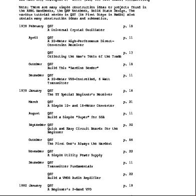
Arrl Qst 6p1j1k
April 2023 0
t-memorandum-circular-no.-1-2016-enhanced-implementing-guidelines-for-the-expanded-students-grats-in-aid-program-for-poverty-allevaiton-esgp-pa.pdf 6j5510
December 2021 0
Indikator Sehat 4134
May 2020 8