Hva30 Very Low Frequency Hipot Tester Operating Manual 3t4t20
This document was ed by and they confirmed that they have the permission to share it. If you are author or own the copyright of this book, please report to us by using this report form. Report 3i3n4
Overview 26281t
& View Hva30 Very Low Frequency Hipot Tester Operating Manual as PDF for free.
More details 6y5l6z
- Words: 5,942
- Pages: 35
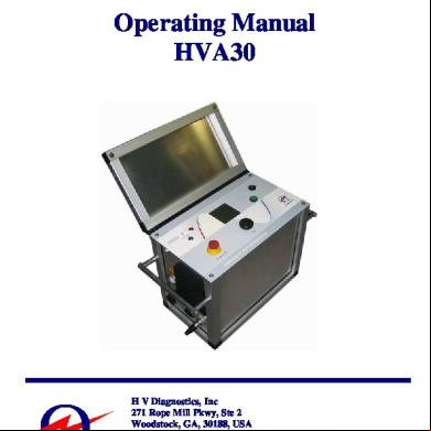
Operating Manual HVA30
H V Diagnostics, Inc 271 Rope Mill Pkwy, Ste 2 Woodstock, GA, 30188, USA Phone: +1 678-445-2555 Fax: +1 678-445-2557 Website: www.hvdiagnostics.com E-mail: [email protected]
Operating Manual HVA30
2
Ver. 1.1 10/2005
Copyright 2005 HV Diagnostics Inc. All rights reserved. No part of this publication may be reproduced, transmitted, stored, or translated in hardcopy or electronic form without the written consent of HV Diagnostics Inc, USA.
NOTE: The information presented in this instruction manual is believed to be accurate and correct for the intended use of this product. Should this instrument be used for other applications and purposes not covered herein, please HV Diagnostics Inc to validate its suitability. This manual, all of its contents and the instruments specifications are subject to change without notice.
Operating Manual HVA30
3
Ver. 1.1 10/2005
Warranty
HV Diagnostics Inc provides a one-year warranty from the original purchase date of instrument for all necessary parts and labor. This warranty and our liability is limited to replacing or repairing, at our discretion, the defective equipment. Equipment that is returned to our company must be suitably packed and all shipped items must be prepaid and insured. This warranty does not include normal consumable items like lamps, paper rolls, printer ribbons, batteries or other expendable items. No other warranties are expressed or implied. This warranty will be voided in the event of abuse, incorrect operation and use, unauthorized modification or repairs or failure to perform the specified maintenance as indicated in this operation manual.
Operating Manual HVA30
4
Ver. 1.1 10/2005
Safety Precautions and Prerequisites •
All equipment to be high potential tested must be de-energized and properly isolated from all power sources. All equipment grounds must remain in place.
•
All high potential test equipment cable connections must be clean and secure. Separate equipment ground connections should be used. Ground integrity must be maintained at all times.
•
Avoid testing alone – always have someone available who is able to render first aid and resuscitation if required.
•
Do not install substitute parts or make unauthorized modifications to the test instrument or its accessories as this may introduce additional risks and unknown hazards. To ensure that all safety features in the instrument are maintained, it is strongly recommended that all repairs and modifications be performed by HV Diagnostics Inc or one of their authorized repair service centers.
•
Before using this test instrument, please read through the operating manual in its entirety. Make sure you clarify any points that you feel unsure or uncertain about before using the instrument. Make sure you are knowledgeable about the proper application, safety, potential hazards involved, and procedures in using the test instrument. The awareness for safety, an integral part of the job, cannot be over emphasized. Safety is the responsibility of the /operator.
•
All personnel operating the high potential test equipment must wear high voltage gloves. the class rating/voltage of all protective devices (e.g. rubber blankets) to ensure proper protection.
•
Use suitable barriers, barricades, or warnings to keep persons not directly involved with the work away from test activities. Personnel must be notified to prevent other workers, as well as the general public, from entering the high potential test area.
•
Vacuum bottles must only be high potential tested with AC. Dangerous X-rays can be produced when vacuum bottles are high potential tested above their rating with DC.
•
Since some electrical apparatus such as cables are essentially capacitors, they can hold a charge after being exposed to a high potential test. These electrical apparatus must therefore remain grounded for sufficient time to drain off any remaining charge. Never assume that a piece of equipment that has been high potential tested is safe to handle without using the necessary safety equipment and grounding procedures. Always treat exposed connectors and conductors as potential electric shock hazards.
•
All auxiliary electrical apparatus such as switchgear, surge arresters etc must be isolated from the test source and device under test (DUT).
•
The test leads must always be disconnected from the device under test (DUT) before attempting to disconnect from the test equipment. The ground connections must be the first made and the last removed. Any interruption of the grounding connection may create an electric shock hazard.
Operating Manual HVA30
5
Ver. 1.1 10/2005
Table of Contents 1. Introduction……………………………………………………….7 2. Application………………………………………………………..7 3. Special Features…………………………………………………..8 4. Safety Features……………………………………………………9 5. Specifications……………………………………………………10 6. Front Description………………………………………….11 7. Side Description…………………………………………...12 8. Used………………………………………………………14 9. Connecting up the Test Instrument………………………………16 10. Controlling the Interface……………………………………18 11. Performing a Quick Manual Test………………………………...19 12. Setting up an Automatic Test Sequence………………………….22 13. Full Test Sequence………………………………………………..25 14. Reports……………………………………………………………30 15. Settings Menu…………………………………………………….32 16. Optional Accessories….………………………………………….33
Operating Manual HVA30
6
Ver. 1.1 10/2005
1. Introduction: The model HVA is an easy to use, single piece, microprocessor based, field portable, fully automatic DC and VLF (Very Low Frequency) high voltage test instrument developed for the high potential testing of the insulation dielectrics of various types of electrical apparatus. 2. Application: The HVA test instrument is designed to perform high voltage insulation testing of various types of electrical apparatus. These applications include, but are not limited to, those testing requirements involving highly capacitive loads such as cables and generators. Other testing applications include switchgear, transformers, rotating machines, insulators, bushings etc. In cable testing applications, the HVA is capable of testing both extruded (such as XLPE) and laminated cables (such as PILC). In addition, the HVA can be used for testing both the cables main insulation section as well as the cable’s jacket/sheath. Both DC (positive and negative with respect to ground) and AC VLF Sinewave and Squarewave outputs are included as standard. Test sequences according to the relevant test standards can be automatically or manually implemented. This flexibility allows the instrument to be used on a multitude of different applications requiring either high voltage AC or DC. The instrument also has a sophisticated Arc management control system allowing s to select various tripping or fault condition modes. The instrument measures and records the capacitance, resistance, dielectric breakdown voltage, RMS current and applied voltage of the device under test.
Operating Manual HVA30
7
Ver. 1.1 10/2005
3. Special Features: 3.1. Optimized Frequency Selection: The HVA has the ability to optimize the frequency when testing capacitive loads. Its does this automatically and without having to restart the instrument. 3.2. Fully Automatic Test Sequences: The HVA can be easily programmed to follow a particular test sequence, applying defined test voltages, durations, and waveforms. 3.3. Easy to use Menu Guided, single pushbutton operation. 3.4. True Symmetrical Sinusoidal and Squarewave outputs waveforms that are load independent within the specified load range of the equipment. 3.5. Built in Memory allows the storing of automatic test sequences and test reports to allow reviewing or ing of test results to a Windows compatible PC. 3.6. Short Circuit protected with active arc management regulation to avoid the usual nuisance tripping of other conventional HV test equipment. 3.7. Both Negative and Positive DC Outputs and Variable Frequency VLF outputs in both Sinewave and Squarewave. 3.8. Real Time Output Voltage Display. The actual instantaneous output voltage is displayed on the test instrument LCD display. 3.9. Automatic load measurement without having to make several connections to the device to be tested before high voltage testing can commence. 3.10. No mechanical moving parts or oil is used in the generation or insulation of the high voltage inside the instrument. This minimizes maintenance and improved durability and reliability of the test instrument.
Operating Manual HVA30
8
Ver. 1.1 10/2005
4. Safety Features: 4.1. Short Circuit and Transient protected. 4.2. Status Display of all important safety interlocks and functions. 4.3. Safe easy-to-use operation with Local Emergency Off Switch with key lockout facility. 4.4. Remote Emergency Off Interlock: For connection to a foot switch or gate switch or another remote Emergency off pushbutton for example. This interlock also provides a switch facility to connect to a green (HV Off) or red (HV ON) remote external lights (not provided). 4.5. Fully integrated discharge and transient circuit to safely ground the DUT after testing and protect the unit from transient over voltages respectively. 4.6. Zero start interlock. 4.7. Initial load clearance test at reduced voltages to check if any shorts or grounds are present before high voltage testing commences. 4.8. Option: External Voltage Proof up to 10kVrms
Operating Manual HVA30
9
Ver. 1.1 10/2005
5. Specification: Input Voltage Output Voltage
Voltage Resolution Voltage Accuracy Output Current Current Resolution Current Accuracy Output Frequency (AC) Output Power Resistance Range Max. Load Capability (@ max. voltage) (Freq. can be selected in steps of 0.01Hz from 0.1Hz) Metering
Duty Memory Computer Interface HV Cable Test Lead Operating Temperature Storage Temperature Relative Humidity Weight Dimensions (LxWxH)
110V – 230V (48-62Hz) - 400VA AC Sinusoidal Voltage 0-33kV Peak (23kV rms) AC Squarewave Voltage 0-30kV DC Voltage 0-30kV (plus and minus) 100V across full range +/- 1% of measuring range 0-15mA 1uA +/- 1% of measuring range 0.02 to 0.1Hz in increments of 0.01Hz 150W 100k.Ohm to 5G.Ohm 0.5uF @ 0.1Hz (5000ft/1.5km of Cable)* 1.0uF @ 0.05Hz (10 000ft/3km of Cable)* 2.5uF @ 0.02Hz (25 000ft/7.6km of Cable)* 5.0uF @ reduced voltages and frequencies (50 000ft/15km of Cable)* Digital Display of the Voltage and Current (True RMS), Capacitance, Resistance, Flashover Voltage, Time and Real time “oscilloscope” type display of actual output voltage. Continuous 50 Test Records in non-volatile built-in memory. RS232 port. Standard is 15 ft (4.5 m) with alligator clamp – other lengths and clamp/connectors are available. 20 to 113F / -5 to 45C -13 to 155F / -25 to 70C 0-80% non-condensing. 44 lbs / 20kgs 17”x14”x10” (430x360x250mm) *Based on a typical 100pf/ft (330pf/m) cable.
Operating Manual HVA30
10
Ver. 1.1 10/2005
6. Front Description:
Figure 1: 1
Emergency OFF
Emergency Off with Latch. To release latch, rotate the switch. When depressed, emergency off is activated. When released, emergency off is deactivated and HV may be activated.
2
LED Green
High Voltage is OFF when this light is activated
3
LED Red
High Voltage ON (DANGER) when this light is activated.
4
Graphic Display Navigation Wheel / Knob
5 6
High Voltage ON/OFF
7
Power ON/OFF Key
Operating Manual HVA30
128 x128 Backlight Display ENTER /SELECT – Press Wheel SCROLL UP or DOWN – Rotate left or Right Pressing this button within 10 seconds after High Voltage is Released by test instrument (see display) will activate HV Output. Key Switch: This switch turns the unit on and off. Removal of the key in the OFF position will lockout the unit and HV will not be able to be activated. This is a useful feature to prevent unauthorized powering up of the instrument.
11
Ver. 1.1 10/2005
7. Side Description:
6
Figure 2: 5 4
1
3 2
1
Earth Connection
This is the first connection that should be made and the last to be removed. Connect to the ground of the DUT. Make sure earth cable is securely connected to this connector so that it cannot come loose inadvertently.
2
Main Plug
110V – 230V 50/60 Hz
3
External Remote Control Interlock Plug
4
Main Switch ON/OFF
5
High Voltage Output Connector
6
Air Filter
Operating Manual HVA30
PIN1 and PIN2 have to be short circuited to allow HV operation. This port can also be connected to a remote emergency off or other switch such as a gate, foot pedal or dead man switch. For all pin connections – please see Figure 3 below. Integrated magnetic auto-resetable “fuse” 6A. The fuse will reset on turning switch “OFF” and then “ON” again. This connects to the HV Test Lead. To Connect HV test lead, screw the plug of the HV test lead into this socket until hand tight and firm. Attention: Never disconnect High Voltage Connector without first ensuring that the device under test has been discharged and grounded and the key switch is off. Check air filter once a year. To check it, unclip outside plastic grill guard. If necessary replace it.
12
Ver. 1.1 10/2005
PINOUT Connections for External Remote Control Interlock Plug This plug provides an interlock for the remote switch such as a door interlock or dead man switch(s). Connection should be made using 600V rated, greater than 18 gauge or 1mm2 twisted pair type cable (not supplied as standard with the instrument). A mating plug is provided with a shorting wire in the event that an external interlock is not used. The PIN 1 and PIN2 should be closed (shorted) before the instrument’s High Voltage can be turned on. External 12V lamps can be used and connected onto PIN5 (RED lamp recommended for HV is ON) and PIN 6 (GREEN recommended for when HV is OFF). Both lamps will source the 12V from the HVA instrument and both lamps need to be grounded via PIN 7. The maximum output from the 12V supply is 100mA per light, so each lamp must not exceed 1.2 Watts.
PIN1 PIN2 PIN3 PIN4 PIN5 PIN6 PIN7
Interlock Interlock Not in Use Not in Use Lamp High Voltage On Lamp High Voltage OFF GND
Figure 3:
Operating Manual HVA30
13
Ver. 1.1 10/2005
Used: A description of some Key used in the Instrument Interface and the Operation Manual: Term Used Manual Mode
Description A Quick Test Mode that minimizes the amount of supplied information and settings input before starting a test. This mode is useful if you want to quickly perform a test without supplying information of the test for reporting purposes. A report will still be generated if the selects to Save a report, but most site and customer specific information will be left blank. The manual test can apply DC (both Positive OR negative polarity), VLF Squarewave or VLF Sinewave. The Test Duration can be set. The Burn Mode can be set to ON or OFF with a defined Dwell time if ON selected.
Automatic Test Sequence
An automatic test sequence is a particular test sequence that has been configured at some point by an operator that allows an automatically controlled sequence of events to occur. The Voltage levels, Voltage Steps, Times, Waveforms, Trip modes can all be predefined in an automatic test sequence. A good application of this is when a particular testing standard needs to be applied to a DUT- such as IEEE, IEC etc. The Instrument will then perform a high voltage test according to the parameters specified in that testing standard. Maintenance, Acceptance and Other Tests can all be preconfigured for use in the field. Once set up, the automatic sequences remain in the memory on the instrument even after a power shutdown. New operators not familiar with a particular testing standard, then just have to select the correct sequence, without having to know or the exact requirements of the testing standard. A Setup Automatic test sequence is easy to identify once created by the advanced naming methodology: For Example a typical Automatic Test Sequence may be: “15kV XLPE Cable Maintenance Test Sequence”
Burn Mode: TRIP or ON (ACTIVE)
Two options are available for the BURN MODE setting. TRIP and ON. If an arc is detected during a high potential test, then depending on the setting of the Burn Mode, the Instrument will either TRIP out or Condition the fault under a controlled “Burn” mode. TRIP Setting: The Unit, on detecting a arc, turns off the output
Operating Manual HVA30
14
Ver. 1.1 10/2005
Term Used
Description voltage, reduces the DUT voltage to zero volts through a discharge circuit and then records the Time to Tripping. BURN MODE ON: This will cause the instrument on the detection of an arc, to continue to try and energize the DUT. If the arc continues, the instrument will continue to apply power to the arc, thereby conditioning the area surrounding the arc location. If ON is selected, then the operator must specify the DWELL time of the fault conditioning mode. For example, if a 1-minute dwell time is selected, on the detection of arc (if one occurs), the unit will apply power to DUT for one full minute after the arc occurred. The unit will then automatically turn off the high voltage and reduce the applied test voltage to the DUT to zero.
DC
This is a single polarity, selectable for either positive or negative to ground. Normally Negative with respect to ground is used. It is not recommended to use this waveform for testing of extruded cables like XLPE. The leakage current detected during a DC test is due to the resistive components of the dielectric being tested and may include the resistive leakage currents across the terminations.
VLF
VLF stands for Very Low Frequency and is typically between 0.01 and 0.1Hz. The usual frequency selected is 0.1 Hz. That means one cycle every 10 seconds. It may be required depending on the high loading conditions to reduce the frequency to below 0.1Hz. The frequency should however be kept as close to 0.1Hz as possible and this is done by the instrument in the 0.1Hz/Auto mode. SINEWAVE: This is the default VLF waveform that should be applied during testing. A Sinewave is the same waveform found as the power frequency waveform which is also a Sinewave at 50 or 60Hz depending on the country. The Value selected during testing and the measured value is the RMS or Root Mean Square. This is how most AC waveforms are measured. The Peak of a Sinewave is 1.414 multiplied by the RMS value. SQUAREWAVE: The square wave is also sometimes called rectangular, trapezoidal or cosines. The value selected during testing and the measured value is the peak of the Squarewave.
Frequency
Operating Manual HVA30
AUTO ADJUST: This mode will maximize the output frequency to the highest possible value, load permitting. The instrument can accommodate 0.5µF at 22kV RMS or 31kV Peak (sinusoidal). If the load is higher that 0.5 µF then the instrument will automatically reduce the frequency to the next lowest value possible. The frequency selected in this mode will depend on the load and voltage applied during the test, as this will determine the power required. A maximum capacitive load of 5µF is possible.
15
Ver. 1.1 10/2005
8. Connecting Up the Test Instrument: Safe operation requires strict adherence to the recommended grounding procedures. The HVA test hook-up to a cable or other electrical apparatus requires three connections. It is important that these connections are made correctly, securely and in the correct sequence. The 110/220V Power Supply Cable should be connected to the Point 2 of Figure 2. Do not turn the unit ON as yet. If the unit powers up automatically (if the main ON/OFF switch was accidentally left in the ON position) then simply turn off the unit at Main ON/OFF switch (Position 4 of Figure 2, Page 12). It is always preferable to use a grounded power supply. If using the optional AC Power Pack, then connect the supplied interconnecting power supply cable from the AC power pack to the HVA. There is no need to ground the power pack as this is done internally through the HVA. The Ground Cable should be connected to the HVA instrument at Point 1 as shown on Figure 2, Page 12. The other end of the ground cable needs to be connected to the DUT’s ground point. In the case of a cable, this will be a grounded concentric neutral / ground point of the cable or the station ground bar. See Figure 4, Page 17. The HV Test Lead is a coaxial conductor made up of the center conductor and an outside Shield Return that should remain at ground potential. The return shield is internally connected to ground in the HV plug that is located at Position 5 of Figure 2, Page 12. Connect the HV Test lead to the HVA test instrument by screwing in the single HV Plug, which is located on one end of the HV test cable. Make sure the plug is securely screwed into the HV socket. Then connect the other end of the HV Test Cable to the device under test (DUT). To do this you will need to connect the HV test lead Shield Return to the ground point of the test object (DUT). The HV Conductor connector will need to be connected to the center conductor of the DUT. In the case of a cable this will be the main center conductor of the cable. See Figure 4, Page 17. The HV Test Lead connection is made before each test and is the last connection to be made before starting the test. Operating Manual HVA30
16
Ver. 1.1 10/2005
DUT Device under Test
HV Test Lead
Ground Cable Station Ground
Figure 4: Connection Diagram for Cable Note: The Ground Cable can be either a green and yellow striped cable or a bare copper braided cable. The HV Test Lead can be a Red jacketed HV cable with Alligator Clamps on both the HV and Screened Ground terminations or a Larger White Neoprene Jacketed cable with a Quick coupling connector for the HV termination and a large alligator for the screened ground connection.
HV Test Lead
Ground Cable
Power Cable 110220V 50/60Hz
Operating Manual HVA30
17
Ver. 1.1 10/2005
Power Supply Cable
9. Controlling The Interface: Once all the electrical connections have been made and have been rechecked, turn ON the HVA test instrument. Both the Side On/off switch and the key switch on the top front plate need to be in the ON position. After the quick boot up, the HVA30 will display the main Menu screen on the LCD.
To Select any item press down / click the main control knob (similar to clicking a computer mouse). To Scroll to different menu items, rotate the main control knob. Some Key Text Entry Notations < Means Backspace and delete _ Means Space x Means Accept Field and Exit Both Numeric (0,1,2….) and Alpha (ABC…) characters can be selected. Certain fields have restrictions on the number or type of characters that can be used. Rotations of the control knob will allow all those permissible characters to be displayed and selected if required by the operator.
Operating Manual HVA30
18
Ver. 1.1 10/2005
10. Performing A Quick Manual Test: Once all the electrical connections have been made and have been rechecked, turn ON the HVA test instrument. Both the Side On/off switch and the key switch on the top front plate need to be in the ON position. After the quick boot up, the test instrument will display the main Menu screen as shown below. Step
Description
1
Main Menu
Display
Action Select Manual Mode on the Main Menu.
(First Screen after boot up)
2
1. If you want to start a test immediately with previously used settings then select “START” and Goto Step 6.
Manual Mode Startup Screen
2. To Setup the applied settings for a Manual test, like waveform type, Scroll and Select “SETUP” 3. TRIP OUT ON ARC: If an Arc occurs, the instrument will turn off HV automatically. 4. BURN ON ARC: If an Arc occurs, the instrument will continue to apply power to the DUT, conditioning the faulted area. 5. Timer: This is the defined time duration of the test. A value of 30 minutes for example will mean that the test, once started will continue for 30minutes at which point the instrument will automatically terminate the test and disconnect the applied voltage.
Operating Manual HVA30
19
Ver. 1.1 10/2005
Step
Description
3
Manual Mode Setup: Waveform Type
Display
Action 6. Select the Waveform type you want to apply to the DUT.
7. Select “CANCEL” to go back. (Sinewave has been selected in this example.)
4
Manual Mode Setup: Select Frequency If Sinewave is chosen, you need to select frequency.
Select Frequency for Sinewave. 0.1Hz/Auto is normally chosen. Select Cancel to return.
5
Manual Mode Setup: Test Duration
Select the Duration the Test Time.
6
Manual Mode Start
Press the Start Button to start the test. Note: It is possible to set the applied test voltage before initiating the Start of the test.
Operating Manual HVA30
20
Ver. 1.1 10/2005
Step
Description
7
Manual Mode HV Activate Screen
Press the Green I/O Push button to activate High Voltage.
8
Manual Mode Active MANUAL MODE
The applied output voltage waveform that was selected will graphically appear on the screen. The load parameters will also be measured and displayed. The measured RMS voltage and current will be shown after one cycle has elapsed.
9
Manual Mode Active MANUAL MODE (Cont.)
The measured voltage (of 10kV rms) is shown. The Timer counts down. The measured load parameters are displayed. Pressing the Control knob activates the STOP button and terminates the test.
Operating Manual HVA30
Display
Action
Note that there is a 10 second window to do this before screen goes back to step 6 above. To escape, rotate main control knob to go back to Step 6 above.
21
Ver. 1.1 10/2005
11. Setting up an Automatic Test Sequence:
Step
Description
1
Main Menu
Display
Action Select Reports and Setup on Main Menu.
(First Screen after boot up)
2
Reports Setup Menu
Select the Edit Auto Test Seq. to add a new test sequence.
3
Auto Test Seq. Edit/Create/New Automatic Test Sequence
Select NEW to create a new Automatic Test Sequence
4
Auto Test Seq. Specify DUT
Specify the DUT (Device under Test). Rotate the knob to toggle to different electrical apparatus such as Cable, Motor, Generator, etc.
5
Auto Test Seq. Specify Voltage Rating of DUT:
The operator needs to specify the DUT rated voltage. This is not the test voltage that will be applied but is used for reporting purposes, e.g. rated line voltage in this example is 6.6kV.
Operating Manual HVA30
22
Ver. 1.1 10/2005
Step
Description
Display
Action
6
Auto Test Seq. Specify Type of Insulation of DUT
Scroll through some options of typical DUT’s insulation types like XLPE, PILC, EPR, PVC, etc. A HYBRID insulation is for a combination of several types of insulation.
7
Auto Test Seq. Specify Type of Testing to be Performed
Scroll to select either Acceptance or Maintenance to choose the type of test to be performed.
8
Auto Test Seq. Specify Type of Waveform
Select the Waveform type to be applied to the DUT. Scroll to select either: Sine (for Sinewave) Squarewave DC Plus DC Minus
9
Auto Test Seq. Specify the Frequency
Select the Applied Frequency if Sinewave or Squarewave was chosen above. 0.1Hz/Auto is normally chosen.
10
Enter the number of voltage steps to be applied to the DUT.
Auto Test Seq. Specify Number of Steps
For example: If the test requires two voltage levels to be applied to the DUT; then select 2 Steps. Example: 4kV and 8kV
Operating Manual HVA30
23
Ver. 1.1 10/2005
Step
Description
11
Auto Test Seq. Specify Voltages for Each Step
Display
Action Enter the voltage level for each individual step. The instrument will automatically select the next step to be set until number of specified steps have been defined.
Auto Test Seq. Specify Test Duration of Each Step
Enter the test duration in minutes for each step.
13
Auto Test Seq. Specify the Current Limit
8. TRIP OUT ON ARC: If an Arc occurs, the instrument will turn off HV automatically. 9. BURN ON ARC: If an Arc occurs, the instrument will continue to apply power to the DUT, conditioning the faulted area.
14
Auto Test Seq. Save the Test Sequence
The test sequence can now be saved. The new test sequence will now be permanently stored in the instrument’s memory for future use even if unit is powered off and then on again.
12
Operating Manual HVA30
The instrument will automatically select the next step to be set until number of specified steps have been defined.
24
Ver. 1.1 10/2005
12.
Full Test Sequence – Extended Reporting:
Step
Description
1
Main Menu
Display
Action Select Start A New Test on the Main Menu. OR select Use Last Test Sequence if that is what you want to initiate.
(First Screen after boot up)
2
Report Active (Yes or No)
If Yes is selected then a report will be generated. If No is selected then a test can still be performed but no a report will be stored.
3
Specify DUT
Specify the DUT (Device under Test). Rotate the knob to toggle to different electrical apparatus such as Cable, Motor, Generator etc.
4
Specify Voltage Rating of DUT:
The operator needs to specify the DUT rated voltage. This is not the test Voltage that will be applied but is used for reporting purposes e.g. the rated ling voltage. In this example the voltage is 11kV.
Operating Manual HVA30
25
Ver. 1.1 10/2005
Step
Description
5
Specify Type of Insulation of DUT
Scroll through some options of typical DUT’s insulation types like XLPE, PILC, EPR, PVC etc. A HYBRID insulation is for a combination of several types of insulation.
6
Report Title
This is the Title of the test report. It is also used to store the file of the report in memory. This is typically the Cable number / ID for a cable test. The name allows for both alpha and numeric values and is totally up to the operator.
7
Specify a Phase
This field allows the operator to specify the phase of the circuit being tested. Such as A or RED phase. The operator can select more than one phase if required.
8
Specify Company Name
Self-Explanatory.
9
Specify Region Name
Self-Explanatory.
Operating Manual HVA30
Display
Action
26
Ver. 1.1 10/2005
Step
Description
10
Specify a Station Name
Self-Explanatory.
11
Specify the Line Length
This field has nothing to do with any calculation of measurement. It is purely used for reporting purposes. The units of measurement are feet or meters depending on the Units selected in the Settings menu.
12
Specify the Size of the DUT
For a cable this will be the size of the conductor typically. For a Motor this may be the Horse Power or Kilowatts.
13
Specify the Manufacturer Name
Self-Explanatory.
14
Specify a Work Order
Self-Explanatory.
Operating Manual HVA30
Display
Action
27
Ver. 1.1 10/2005
Step
Description
Display
Action
15
Specify the Operator Name
Self-Explanatory.
16
Select an Automatic Test Sequence or Manually Perform the Test
Selecting the AUTO SEQ. will allow the operator to select a test sequence from a list of existing predefined test sequences. GOTO Step 17 Selecting MANUAL will allow the operator to perform a test manually. To continue please GOTO Section 11 Step 2 above.
17
Select the AUTO TEST SEQUENCE
Scroll down to select the test sequence from the list of Test Sequences. If the Test Sequence required is not listed then an Automatic Test Sequence will need to be set up. Please see page 22.
18
TEST SEQUENCE DETAILS
The parameters of the Test Sequence are displayed to allow the operator to view them before allowing the instrument to automatically apply them.
19
HV Activate Screen
Press the Green I/O Push button to activate High Voltage. Note there is 10 seconds to do this before screen goes back to step 18 above. To escape, rotate main control knob to go back to Step 6 above.
Operating Manual HVA30
28
Ver. 1.1 10/2005
Step
Description
20
Active Automatic Mode
The applied test sequence that was selected will be applied to the DUT. The output waveform will graphically appear on the screen. The load parameters will also be displayed. The measured RMS voltage and current will be shown after one cycle has elapsed.
21
Test Complete
After an Automatic Test is completed, the results can be viewed on the screen if selected.
Operating Manual HVA30
Display
Action
29
Ver. 1.1 10/2005
13.
Reports:
Step
Description
1
Main Menu
Display
Action Select Reports and Setup
(First Screen after boot up)
2
Reports and Setup Screen
3
View Reports
The Reports are listed in Date order. The total number of Reports is shown in the heading in this case a total of 6 reports are in memory. Currently report Number 6 of 6 is displayed. The Page number is on the top right of the page for that particular report. In this case page 1 of 3 of report number 6.
4
View Report Pages
Page 2 of 3 of report number 6.
Operating Manual HVA30
30
Ver. 1.1 10/2005
Step
Description
5
View Report Pages
Operating Manual HVA30
Display
Action Page 3 of 3 of report number 6.
31
Ver. 1.1 10/2005
14.
Settings Menu:
Step
Description
1
Main Menu
Display
Action Select Reports and Setup on Main Menu.
(First Screen after boot up)
2
Select Set Date and Time to set the Date and Time.
Instrument Settings
Reporting: Extended: for full reporting functionality. Basic: for minimum reporting functionality. Allow for quick startup and testing with the bare minimum of information required to make up the test report. Startup: Select the default startup screen either Main Menu or Manual Mode. Language: Select which Language to use for the interface. System Info: For information such as temperature and the latest installed firmware version and the last calibration date.
3
System Info: For information such as temperature and the latest installed firmware version and the last calibration date.
System Info
Operating Manual HVA30
32
Ver. 1.1 10/2005
15.
Optional Accessories:
16.1 HV Test Lead with Quick Coupling Connecter. 16.2 Power Pack: Auxiliary AC Power Pack to independently power up instrument when external power source is not available. When the Power Pack is fully charged there is approximately 20 minutes of power for the HVA30 unit at full power, longer if not used at full power. Figure 5: Connections for Power Pack
On/Off Switch For Power Pack
AC Output Plug
Unit Charging Indicator Light
Charger Input Plug
Important Note: DO NOT USE Power Pack for AC Supply of HVA when Power Pack is in charge mode! To Charge Power Pack the standard power cord provided should be plugged into the Charge Input socket. A red light indicates that the unit is charging. A green light indicated that the unit is fully charged. See Figure 5 above.
Operating Manual HVA30
33
Ver. 1.1 10/2005
To Use Power Pack as AC Source connect one end of the cord provided with the unit into the AC Output on the Power Pack and the opposite end should be plugged into the AC Input on the HVA30. See Figure 5 above. 16.3 ATA Approved Transport Case: This is a protective case for the transport and shipping of the HVA30. 16.4 External Voltage Monitoring System With this option the HVA warns the if an external source is connected to the output of the HVA. Maximum Voltage: 10kVrms Detected Minimum Voltage: 200Vrms This includes: - Built in buzzer, active if 50/60Hz external voltage is detected Buzzer stops if external voltage is removed. - RED HV on lamp flashing if external Voltage is detected - Interface shows corresponding messages (current applied voltage, maximum applied voltage since first occurrence) This message has to be acknowledged by the . Attention! In the case of an external voltage is applied follow these and your local safety guidelines: - Do not unplug the HVA connector - Remove external voltage - Make sure that the fault can not occur again - Discharge and ground the Device Under Test Message shown:
Operating Manual HVA30
34
Ver. 1.1 10/2005
Operating Manual HVA30
35
Ver. 1.1 10/2005
H V Diagnostics, Inc 271 Rope Mill Pkwy, Ste 2 Woodstock, GA, 30188, USA Phone: +1 678-445-2555 Fax: +1 678-445-2557 Website: www.hvdiagnostics.com E-mail: [email protected]
Operating Manual HVA30
2
Ver. 1.1 10/2005
Copyright 2005 HV Diagnostics Inc. All rights reserved. No part of this publication may be reproduced, transmitted, stored, or translated in hardcopy or electronic form without the written consent of HV Diagnostics Inc, USA.
NOTE: The information presented in this instruction manual is believed to be accurate and correct for the intended use of this product. Should this instrument be used for other applications and purposes not covered herein, please HV Diagnostics Inc to validate its suitability. This manual, all of its contents and the instruments specifications are subject to change without notice.
Operating Manual HVA30
3
Ver. 1.1 10/2005
Warranty
HV Diagnostics Inc provides a one-year warranty from the original purchase date of instrument for all necessary parts and labor. This warranty and our liability is limited to replacing or repairing, at our discretion, the defective equipment. Equipment that is returned to our company must be suitably packed and all shipped items must be prepaid and insured. This warranty does not include normal consumable items like lamps, paper rolls, printer ribbons, batteries or other expendable items. No other warranties are expressed or implied. This warranty will be voided in the event of abuse, incorrect operation and use, unauthorized modification or repairs or failure to perform the specified maintenance as indicated in this operation manual.
Operating Manual HVA30
4
Ver. 1.1 10/2005
Safety Precautions and Prerequisites •
All equipment to be high potential tested must be de-energized and properly isolated from all power sources. All equipment grounds must remain in place.
•
All high potential test equipment cable connections must be clean and secure. Separate equipment ground connections should be used. Ground integrity must be maintained at all times.
•
Avoid testing alone – always have someone available who is able to render first aid and resuscitation if required.
•
Do not install substitute parts or make unauthorized modifications to the test instrument or its accessories as this may introduce additional risks and unknown hazards. To ensure that all safety features in the instrument are maintained, it is strongly recommended that all repairs and modifications be performed by HV Diagnostics Inc or one of their authorized repair service centers.
•
Before using this test instrument, please read through the operating manual in its entirety. Make sure you clarify any points that you feel unsure or uncertain about before using the instrument. Make sure you are knowledgeable about the proper application, safety, potential hazards involved, and procedures in using the test instrument. The awareness for safety, an integral part of the job, cannot be over emphasized. Safety is the responsibility of the /operator.
•
All personnel operating the high potential test equipment must wear high voltage gloves. the class rating/voltage of all protective devices (e.g. rubber blankets) to ensure proper protection.
•
Use suitable barriers, barricades, or warnings to keep persons not directly involved with the work away from test activities. Personnel must be notified to prevent other workers, as well as the general public, from entering the high potential test area.
•
Vacuum bottles must only be high potential tested with AC. Dangerous X-rays can be produced when vacuum bottles are high potential tested above their rating with DC.
•
Since some electrical apparatus such as cables are essentially capacitors, they can hold a charge after being exposed to a high potential test. These electrical apparatus must therefore remain grounded for sufficient time to drain off any remaining charge. Never assume that a piece of equipment that has been high potential tested is safe to handle without using the necessary safety equipment and grounding procedures. Always treat exposed connectors and conductors as potential electric shock hazards.
•
All auxiliary electrical apparatus such as switchgear, surge arresters etc must be isolated from the test source and device under test (DUT).
•
The test leads must always be disconnected from the device under test (DUT) before attempting to disconnect from the test equipment. The ground connections must be the first made and the last removed. Any interruption of the grounding connection may create an electric shock hazard.
Operating Manual HVA30
5
Ver. 1.1 10/2005
Table of Contents 1. Introduction……………………………………………………….7 2. Application………………………………………………………..7 3. Special Features…………………………………………………..8 4. Safety Features……………………………………………………9 5. Specifications……………………………………………………10 6. Front Description………………………………………….11 7. Side Description…………………………………………...12 8. Used………………………………………………………14 9. Connecting up the Test Instrument………………………………16 10. Controlling the Interface……………………………………18 11. Performing a Quick Manual Test………………………………...19 12. Setting up an Automatic Test Sequence………………………….22 13. Full Test Sequence………………………………………………..25 14. Reports……………………………………………………………30 15. Settings Menu…………………………………………………….32 16. Optional Accessories….………………………………………….33
Operating Manual HVA30
6
Ver. 1.1 10/2005
1. Introduction: The model HVA is an easy to use, single piece, microprocessor based, field portable, fully automatic DC and VLF (Very Low Frequency) high voltage test instrument developed for the high potential testing of the insulation dielectrics of various types of electrical apparatus. 2. Application: The HVA test instrument is designed to perform high voltage insulation testing of various types of electrical apparatus. These applications include, but are not limited to, those testing requirements involving highly capacitive loads such as cables and generators. Other testing applications include switchgear, transformers, rotating machines, insulators, bushings etc. In cable testing applications, the HVA is capable of testing both extruded (such as XLPE) and laminated cables (such as PILC). In addition, the HVA can be used for testing both the cables main insulation section as well as the cable’s jacket/sheath. Both DC (positive and negative with respect to ground) and AC VLF Sinewave and Squarewave outputs are included as standard. Test sequences according to the relevant test standards can be automatically or manually implemented. This flexibility allows the instrument to be used on a multitude of different applications requiring either high voltage AC or DC. The instrument also has a sophisticated Arc management control system allowing s to select various tripping or fault condition modes. The instrument measures and records the capacitance, resistance, dielectric breakdown voltage, RMS current and applied voltage of the device under test.
Operating Manual HVA30
7
Ver. 1.1 10/2005
3. Special Features: 3.1. Optimized Frequency Selection: The HVA has the ability to optimize the frequency when testing capacitive loads. Its does this automatically and without having to restart the instrument. 3.2. Fully Automatic Test Sequences: The HVA can be easily programmed to follow a particular test sequence, applying defined test voltages, durations, and waveforms. 3.3. Easy to use Menu Guided, single pushbutton operation. 3.4. True Symmetrical Sinusoidal and Squarewave outputs waveforms that are load independent within the specified load range of the equipment. 3.5. Built in Memory allows the storing of automatic test sequences and test reports to allow reviewing or ing of test results to a Windows compatible PC. 3.6. Short Circuit protected with active arc management regulation to avoid the usual nuisance tripping of other conventional HV test equipment. 3.7. Both Negative and Positive DC Outputs and Variable Frequency VLF outputs in both Sinewave and Squarewave. 3.8. Real Time Output Voltage Display. The actual instantaneous output voltage is displayed on the test instrument LCD display. 3.9. Automatic load measurement without having to make several connections to the device to be tested before high voltage testing can commence. 3.10. No mechanical moving parts or oil is used in the generation or insulation of the high voltage inside the instrument. This minimizes maintenance and improved durability and reliability of the test instrument.
Operating Manual HVA30
8
Ver. 1.1 10/2005
4. Safety Features: 4.1. Short Circuit and Transient protected. 4.2. Status Display of all important safety interlocks and functions. 4.3. Safe easy-to-use operation with Local Emergency Off Switch with key lockout facility. 4.4. Remote Emergency Off Interlock: For connection to a foot switch or gate switch or another remote Emergency off pushbutton for example. This interlock also provides a switch facility to connect to a green (HV Off) or red (HV ON) remote external lights (not provided). 4.5. Fully integrated discharge and transient circuit to safely ground the DUT after testing and protect the unit from transient over voltages respectively. 4.6. Zero start interlock. 4.7. Initial load clearance test at reduced voltages to check if any shorts or grounds are present before high voltage testing commences. 4.8. Option: External Voltage Proof up to 10kVrms
Operating Manual HVA30
9
Ver. 1.1 10/2005
5. Specification: Input Voltage Output Voltage
Voltage Resolution Voltage Accuracy Output Current Current Resolution Current Accuracy Output Frequency (AC) Output Power Resistance Range Max. Load Capability (@ max. voltage) (Freq. can be selected in steps of 0.01Hz from 0.1Hz) Metering
Duty Memory Computer Interface HV Cable Test Lead Operating Temperature Storage Temperature Relative Humidity Weight Dimensions (LxWxH)
110V – 230V (48-62Hz) - 400VA AC Sinusoidal Voltage 0-33kV Peak (23kV rms) AC Squarewave Voltage 0-30kV DC Voltage 0-30kV (plus and minus) 100V across full range +/- 1% of measuring range 0-15mA 1uA +/- 1% of measuring range 0.02 to 0.1Hz in increments of 0.01Hz 150W 100k.Ohm to 5G.Ohm 0.5uF @ 0.1Hz (5000ft/1.5km of Cable)* 1.0uF @ 0.05Hz (10 000ft/3km of Cable)* 2.5uF @ 0.02Hz (25 000ft/7.6km of Cable)* 5.0uF @ reduced voltages and frequencies (50 000ft/15km of Cable)* Digital Display of the Voltage and Current (True RMS), Capacitance, Resistance, Flashover Voltage, Time and Real time “oscilloscope” type display of actual output voltage. Continuous 50 Test Records in non-volatile built-in memory. RS232 port. Standard is 15 ft (4.5 m) with alligator clamp – other lengths and clamp/connectors are available. 20 to 113F / -5 to 45C -13 to 155F / -25 to 70C 0-80% non-condensing. 44 lbs / 20kgs 17”x14”x10” (430x360x250mm) *Based on a typical 100pf/ft (330pf/m) cable.
Operating Manual HVA30
10
Ver. 1.1 10/2005
6. Front Description:
Figure 1: 1
Emergency OFF
Emergency Off with Latch. To release latch, rotate the switch. When depressed, emergency off is activated. When released, emergency off is deactivated and HV may be activated.
2
LED Green
High Voltage is OFF when this light is activated
3
LED Red
High Voltage ON (DANGER) when this light is activated.
4
Graphic Display Navigation Wheel / Knob
5 6
High Voltage ON/OFF
7
Power ON/OFF Key
Operating Manual HVA30
128 x128 Backlight Display ENTER /SELECT – Press Wheel SCROLL UP or DOWN – Rotate left or Right Pressing this button within 10 seconds after High Voltage is Released by test instrument (see display) will activate HV Output. Key Switch: This switch turns the unit on and off. Removal of the key in the OFF position will lockout the unit and HV will not be able to be activated. This is a useful feature to prevent unauthorized powering up of the instrument.
11
Ver. 1.1 10/2005
7. Side Description:
6
Figure 2: 5 4
1
3 2
1
Earth Connection
This is the first connection that should be made and the last to be removed. Connect to the ground of the DUT. Make sure earth cable is securely connected to this connector so that it cannot come loose inadvertently.
2
Main Plug
110V – 230V 50/60 Hz
3
External Remote Control Interlock Plug
4
Main Switch ON/OFF
5
High Voltage Output Connector
6
Air Filter
Operating Manual HVA30
PIN1 and PIN2 have to be short circuited to allow HV operation. This port can also be connected to a remote emergency off or other switch such as a gate, foot pedal or dead man switch. For all pin connections – please see Figure 3 below. Integrated magnetic auto-resetable “fuse” 6A. The fuse will reset on turning switch “OFF” and then “ON” again. This connects to the HV Test Lead. To Connect HV test lead, screw the plug of the HV test lead into this socket until hand tight and firm. Attention: Never disconnect High Voltage Connector without first ensuring that the device under test has been discharged and grounded and the key switch is off. Check air filter once a year. To check it, unclip outside plastic grill guard. If necessary replace it.
12
Ver. 1.1 10/2005
PINOUT Connections for External Remote Control Interlock Plug This plug provides an interlock for the remote switch such as a door interlock or dead man switch(s). Connection should be made using 600V rated, greater than 18 gauge or 1mm2 twisted pair type cable (not supplied as standard with the instrument). A mating plug is provided with a shorting wire in the event that an external interlock is not used. The PIN 1 and PIN2 should be closed (shorted) before the instrument’s High Voltage can be turned on. External 12V lamps can be used and connected onto PIN5 (RED lamp recommended for HV is ON) and PIN 6 (GREEN recommended for when HV is OFF). Both lamps will source the 12V from the HVA instrument and both lamps need to be grounded via PIN 7. The maximum output from the 12V supply is 100mA per light, so each lamp must not exceed 1.2 Watts.
PIN1 PIN2 PIN3 PIN4 PIN5 PIN6 PIN7
Interlock Interlock Not in Use Not in Use Lamp High Voltage On Lamp High Voltage OFF GND
Figure 3:
Operating Manual HVA30
13
Ver. 1.1 10/2005
Used: A description of some Key used in the Instrument Interface and the Operation Manual: Term Used Manual Mode
Description A Quick Test Mode that minimizes the amount of supplied information and settings input before starting a test. This mode is useful if you want to quickly perform a test without supplying information of the test for reporting purposes. A report will still be generated if the selects to Save a report, but most site and customer specific information will be left blank. The manual test can apply DC (both Positive OR negative polarity), VLF Squarewave or VLF Sinewave. The Test Duration can be set. The Burn Mode can be set to ON or OFF with a defined Dwell time if ON selected.
Automatic Test Sequence
An automatic test sequence is a particular test sequence that has been configured at some point by an operator that allows an automatically controlled sequence of events to occur. The Voltage levels, Voltage Steps, Times, Waveforms, Trip modes can all be predefined in an automatic test sequence. A good application of this is when a particular testing standard needs to be applied to a DUT- such as IEEE, IEC etc. The Instrument will then perform a high voltage test according to the parameters specified in that testing standard. Maintenance, Acceptance and Other Tests can all be preconfigured for use in the field. Once set up, the automatic sequences remain in the memory on the instrument even after a power shutdown. New operators not familiar with a particular testing standard, then just have to select the correct sequence, without having to know or the exact requirements of the testing standard. A Setup Automatic test sequence is easy to identify once created by the advanced naming methodology: For Example a typical Automatic Test Sequence may be: “15kV XLPE Cable Maintenance Test Sequence”
Burn Mode: TRIP or ON (ACTIVE)
Two options are available for the BURN MODE setting. TRIP and ON. If an arc is detected during a high potential test, then depending on the setting of the Burn Mode, the Instrument will either TRIP out or Condition the fault under a controlled “Burn” mode. TRIP Setting: The Unit, on detecting a arc, turns off the output
Operating Manual HVA30
14
Ver. 1.1 10/2005
Term Used
Description voltage, reduces the DUT voltage to zero volts through a discharge circuit and then records the Time to Tripping. BURN MODE ON: This will cause the instrument on the detection of an arc, to continue to try and energize the DUT. If the arc continues, the instrument will continue to apply power to the arc, thereby conditioning the area surrounding the arc location. If ON is selected, then the operator must specify the DWELL time of the fault conditioning mode. For example, if a 1-minute dwell time is selected, on the detection of arc (if one occurs), the unit will apply power to DUT for one full minute after the arc occurred. The unit will then automatically turn off the high voltage and reduce the applied test voltage to the DUT to zero.
DC
This is a single polarity, selectable for either positive or negative to ground. Normally Negative with respect to ground is used. It is not recommended to use this waveform for testing of extruded cables like XLPE. The leakage current detected during a DC test is due to the resistive components of the dielectric being tested and may include the resistive leakage currents across the terminations.
VLF
VLF stands for Very Low Frequency and is typically between 0.01 and 0.1Hz. The usual frequency selected is 0.1 Hz. That means one cycle every 10 seconds. It may be required depending on the high loading conditions to reduce the frequency to below 0.1Hz. The frequency should however be kept as close to 0.1Hz as possible and this is done by the instrument in the 0.1Hz/Auto mode. SINEWAVE: This is the default VLF waveform that should be applied during testing. A Sinewave is the same waveform found as the power frequency waveform which is also a Sinewave at 50 or 60Hz depending on the country. The Value selected during testing and the measured value is the RMS or Root Mean Square. This is how most AC waveforms are measured. The Peak of a Sinewave is 1.414 multiplied by the RMS value. SQUAREWAVE: The square wave is also sometimes called rectangular, trapezoidal or cosines. The value selected during testing and the measured value is the peak of the Squarewave.
Frequency
Operating Manual HVA30
AUTO ADJUST: This mode will maximize the output frequency to the highest possible value, load permitting. The instrument can accommodate 0.5µF at 22kV RMS or 31kV Peak (sinusoidal). If the load is higher that 0.5 µF then the instrument will automatically reduce the frequency to the next lowest value possible. The frequency selected in this mode will depend on the load and voltage applied during the test, as this will determine the power required. A maximum capacitive load of 5µF is possible.
15
Ver. 1.1 10/2005
8. Connecting Up the Test Instrument: Safe operation requires strict adherence to the recommended grounding procedures. The HVA test hook-up to a cable or other electrical apparatus requires three connections. It is important that these connections are made correctly, securely and in the correct sequence. The 110/220V Power Supply Cable should be connected to the Point 2 of Figure 2. Do not turn the unit ON as yet. If the unit powers up automatically (if the main ON/OFF switch was accidentally left in the ON position) then simply turn off the unit at Main ON/OFF switch (Position 4 of Figure 2, Page 12). It is always preferable to use a grounded power supply. If using the optional AC Power Pack, then connect the supplied interconnecting power supply cable from the AC power pack to the HVA. There is no need to ground the power pack as this is done internally through the HVA. The Ground Cable should be connected to the HVA instrument at Point 1 as shown on Figure 2, Page 12. The other end of the ground cable needs to be connected to the DUT’s ground point. In the case of a cable, this will be a grounded concentric neutral / ground point of the cable or the station ground bar. See Figure 4, Page 17. The HV Test Lead is a coaxial conductor made up of the center conductor and an outside Shield Return that should remain at ground potential. The return shield is internally connected to ground in the HV plug that is located at Position 5 of Figure 2, Page 12. Connect the HV Test lead to the HVA test instrument by screwing in the single HV Plug, which is located on one end of the HV test cable. Make sure the plug is securely screwed into the HV socket. Then connect the other end of the HV Test Cable to the device under test (DUT). To do this you will need to connect the HV test lead Shield Return to the ground point of the test object (DUT). The HV Conductor connector will need to be connected to the center conductor of the DUT. In the case of a cable this will be the main center conductor of the cable. See Figure 4, Page 17. The HV Test Lead connection is made before each test and is the last connection to be made before starting the test. Operating Manual HVA30
16
Ver. 1.1 10/2005
DUT Device under Test
HV Test Lead
Ground Cable Station Ground
Figure 4: Connection Diagram for Cable Note: The Ground Cable can be either a green and yellow striped cable or a bare copper braided cable. The HV Test Lead can be a Red jacketed HV cable with Alligator Clamps on both the HV and Screened Ground terminations or a Larger White Neoprene Jacketed cable with a Quick coupling connector for the HV termination and a large alligator for the screened ground connection.
HV Test Lead
Ground Cable
Power Cable 110220V 50/60Hz
Operating Manual HVA30
17
Ver. 1.1 10/2005
Power Supply Cable
9. Controlling The Interface: Once all the electrical connections have been made and have been rechecked, turn ON the HVA test instrument. Both the Side On/off switch and the key switch on the top front plate need to be in the ON position. After the quick boot up, the HVA30 will display the main Menu screen on the LCD.
To Select any item press down / click the main control knob (similar to clicking a computer mouse). To Scroll to different menu items, rotate the main control knob. Some Key Text Entry Notations < Means Backspace and delete _ Means Space x Means Accept Field and Exit Both Numeric (0,1,2….) and Alpha (ABC…) characters can be selected. Certain fields have restrictions on the number or type of characters that can be used. Rotations of the control knob will allow all those permissible characters to be displayed and selected if required by the operator.
Operating Manual HVA30
18
Ver. 1.1 10/2005
10. Performing A Quick Manual Test: Once all the electrical connections have been made and have been rechecked, turn ON the HVA test instrument. Both the Side On/off switch and the key switch on the top front plate need to be in the ON position. After the quick boot up, the test instrument will display the main Menu screen as shown below. Step
Description
1
Main Menu
Display
Action Select Manual Mode on the Main Menu.
(First Screen after boot up)
2
1. If you want to start a test immediately with previously used settings then select “START” and Goto Step 6.
Manual Mode Startup Screen
2. To Setup the applied settings for a Manual test, like waveform type, Scroll and Select “SETUP” 3. TRIP OUT ON ARC: If an Arc occurs, the instrument will turn off HV automatically. 4. BURN ON ARC: If an Arc occurs, the instrument will continue to apply power to the DUT, conditioning the faulted area. 5. Timer: This is the defined time duration of the test. A value of 30 minutes for example will mean that the test, once started will continue for 30minutes at which point the instrument will automatically terminate the test and disconnect the applied voltage.
Operating Manual HVA30
19
Ver. 1.1 10/2005
Step
Description
3
Manual Mode Setup: Waveform Type
Display
Action 6. Select the Waveform type you want to apply to the DUT.
7. Select “CANCEL” to go back. (Sinewave has been selected in this example.)
4
Manual Mode Setup: Select Frequency If Sinewave is chosen, you need to select frequency.
Select Frequency for Sinewave. 0.1Hz/Auto is normally chosen. Select Cancel to return.
5
Manual Mode Setup: Test Duration
Select the Duration the Test Time.
6
Manual Mode Start
Press the Start Button to start the test. Note: It is possible to set the applied test voltage before initiating the Start of the test.
Operating Manual HVA30
20
Ver. 1.1 10/2005
Step
Description
7
Manual Mode HV Activate Screen
Press the Green I/O Push button to activate High Voltage.
8
Manual Mode Active MANUAL MODE
The applied output voltage waveform that was selected will graphically appear on the screen. The load parameters will also be measured and displayed. The measured RMS voltage and current will be shown after one cycle has elapsed.
9
Manual Mode Active MANUAL MODE (Cont.)
The measured voltage (of 10kV rms) is shown. The Timer counts down. The measured load parameters are displayed. Pressing the Control knob activates the STOP button and terminates the test.
Operating Manual HVA30
Display
Action
Note that there is a 10 second window to do this before screen goes back to step 6 above. To escape, rotate main control knob to go back to Step 6 above.
21
Ver. 1.1 10/2005
11. Setting up an Automatic Test Sequence:
Step
Description
1
Main Menu
Display
Action Select Reports and Setup on Main Menu.
(First Screen after boot up)
2
Reports Setup Menu
Select the Edit Auto Test Seq. to add a new test sequence.
3
Auto Test Seq. Edit/Create/New Automatic Test Sequence
Select NEW to create a new Automatic Test Sequence
4
Auto Test Seq. Specify DUT
Specify the DUT (Device under Test). Rotate the knob to toggle to different electrical apparatus such as Cable, Motor, Generator, etc.
5
Auto Test Seq. Specify Voltage Rating of DUT:
The operator needs to specify the DUT rated voltage. This is not the test voltage that will be applied but is used for reporting purposes, e.g. rated line voltage in this example is 6.6kV.
22
Ver. 1.1 10/2005
Step
Description
Display
Action
6
Auto Test Seq. Specify Type of Insulation of DUT
Scroll through some options of typical DUT’s insulation types like XLPE, PILC, EPR, PVC, etc. A HYBRID insulation is for a combination of several types of insulation.
7
Auto Test Seq. Specify Type of Testing to be Performed
Scroll to select either Acceptance or Maintenance to choose the type of test to be performed.
8
Auto Test Seq. Specify Type of Waveform
Select the Waveform type to be applied to the DUT. Scroll to select either: Sine (for Sinewave) Squarewave DC Plus DC Minus
9
Auto Test Seq. Specify the Frequency
Select the Applied Frequency if Sinewave or Squarewave was chosen above. 0.1Hz/Auto is normally chosen.
10
Enter the number of voltage steps to be applied to the DUT.
Auto Test Seq. Specify Number of Steps
For example: If the test requires two voltage levels to be applied to the DUT; then select 2 Steps. Example: 4kV and 8kV
Operating Manual HVA30
23
Ver. 1.1 10/2005
Step
Description
11
Auto Test Seq. Specify Voltages for Each Step
Display
Action Enter the voltage level for each individual step. The instrument will automatically select the next step to be set until number of specified steps have been defined.
Auto Test Seq. Specify Test Duration of Each Step
Enter the test duration in minutes for each step.
13
Auto Test Seq. Specify the Current Limit
8. TRIP OUT ON ARC: If an Arc occurs, the instrument will turn off HV automatically. 9. BURN ON ARC: If an Arc occurs, the instrument will continue to apply power to the DUT, conditioning the faulted area.
14
Auto Test Seq. Save the Test Sequence
The test sequence can now be saved. The new test sequence will now be permanently stored in the instrument’s memory for future use even if unit is powered off and then on again.
12
Operating Manual HVA30
The instrument will automatically select the next step to be set until number of specified steps have been defined.
24
Ver. 1.1 10/2005
12.
Full Test Sequence – Extended Reporting:
Step
Description
1
Main Menu
Display
Action Select Start A New Test on the Main Menu. OR select Use Last Test Sequence if that is what you want to initiate.
(First Screen after boot up)
2
Report Active (Yes or No)
If Yes is selected then a report will be generated. If No is selected then a test can still be performed but no a report will be stored.
3
Specify DUT
Specify the DUT (Device under Test). Rotate the knob to toggle to different electrical apparatus such as Cable, Motor, Generator etc.
4
Specify Voltage Rating of DUT:
The operator needs to specify the DUT rated voltage. This is not the test Voltage that will be applied but is used for reporting purposes e.g. the rated ling voltage. In this example the voltage is 11kV.
Operating Manual HVA30
25
Ver. 1.1 10/2005
Step
Description
5
Specify Type of Insulation of DUT
Scroll through some options of typical DUT’s insulation types like XLPE, PILC, EPR, PVC etc. A HYBRID insulation is for a combination of several types of insulation.
6
Report Title
This is the Title of the test report. It is also used to store the file of the report in memory. This is typically the Cable number / ID for a cable test. The name allows for both alpha and numeric values and is totally up to the operator.
7
Specify a Phase
This field allows the operator to specify the phase of the circuit being tested. Such as A or RED phase. The operator can select more than one phase if required.
8
Specify Company Name
Self-Explanatory.
9
Specify Region Name
Self-Explanatory.
Operating Manual HVA30
Display
Action
26
Ver. 1.1 10/2005
Step
Description
10
Specify a Station Name
Self-Explanatory.
11
Specify the Line Length
This field has nothing to do with any calculation of measurement. It is purely used for reporting purposes. The units of measurement are feet or meters depending on the Units selected in the Settings menu.
12
Specify the Size of the DUT
For a cable this will be the size of the conductor typically. For a Motor this may be the Horse Power or Kilowatts.
13
Specify the Manufacturer Name
Self-Explanatory.
14
Specify a Work Order
Self-Explanatory.
Operating Manual HVA30
Display
Action
27
Ver. 1.1 10/2005
Step
Description
Display
Action
15
Specify the Operator Name
Self-Explanatory.
16
Select an Automatic Test Sequence or Manually Perform the Test
Selecting the AUTO SEQ. will allow the operator to select a test sequence from a list of existing predefined test sequences. GOTO Step 17 Selecting MANUAL will allow the operator to perform a test manually. To continue please GOTO Section 11 Step 2 above.
17
Select the AUTO TEST SEQUENCE
Scroll down to select the test sequence from the list of Test Sequences. If the Test Sequence required is not listed then an Automatic Test Sequence will need to be set up. Please see page 22.
18
TEST SEQUENCE DETAILS
The parameters of the Test Sequence are displayed to allow the operator to view them before allowing the instrument to automatically apply them.
19
HV Activate Screen
Press the Green I/O Push button to activate High Voltage. Note there is 10 seconds to do this before screen goes back to step 18 above. To escape, rotate main control knob to go back to Step 6 above.
Operating Manual HVA30
28
Ver. 1.1 10/2005
Step
Description
20
Active Automatic Mode
The applied test sequence that was selected will be applied to the DUT. The output waveform will graphically appear on the screen. The load parameters will also be displayed. The measured RMS voltage and current will be shown after one cycle has elapsed.
21
Test Complete
After an Automatic Test is completed, the results can be viewed on the screen if selected.
Operating Manual HVA30
Display
Action
29
Ver. 1.1 10/2005
13.
Reports:
Step
Description
1
Main Menu
Display
Action Select Reports and Setup
(First Screen after boot up)
2
Reports and Setup Screen
3
View Reports
The Reports are listed in Date order. The total number of Reports is shown in the heading in this case a total of 6 reports are in memory. Currently report Number 6 of 6 is displayed. The Page number is on the top right of the page for that particular report. In this case page 1 of 3 of report number 6.
4
View Report Pages
Page 2 of 3 of report number 6.
Operating Manual HVA30
30
Ver. 1.1 10/2005
Step
Description
5
View Report Pages
Operating Manual HVA30
Display
Action Page 3 of 3 of report number 6.
31
Ver. 1.1 10/2005
14.
Settings Menu:
Step
Description
1
Main Menu
Display
Action Select Reports and Setup on Main Menu.
(First Screen after boot up)
2
Select Set Date and Time to set the Date and Time.
Instrument Settings
Reporting: Extended: for full reporting functionality. Basic: for minimum reporting functionality. Allow for quick startup and testing with the bare minimum of information required to make up the test report. Startup: Select the default startup screen either Main Menu or Manual Mode. Language: Select which Language to use for the interface. System Info: For information such as temperature and the latest installed firmware version and the last calibration date.
3
System Info: For information such as temperature and the latest installed firmware version and the last calibration date.
System Info
Operating Manual HVA30
32
Ver. 1.1 10/2005
15.
Optional Accessories:
16.1 HV Test Lead with Quick Coupling Connecter. 16.2 Power Pack: Auxiliary AC Power Pack to independently power up instrument when external power source is not available. When the Power Pack is fully charged there is approximately 20 minutes of power for the HVA30 unit at full power, longer if not used at full power. Figure 5: Connections for Power Pack
On/Off Switch For Power Pack
AC Output Plug
Unit Charging Indicator Light
Charger Input Plug
Important Note: DO NOT USE Power Pack for AC Supply of HVA when Power Pack is in charge mode! To Charge Power Pack the standard power cord provided should be plugged into the Charge Input socket. A red light indicates that the unit is charging. A green light indicated that the unit is fully charged. See Figure 5 above.
Operating Manual HVA30
33
Ver. 1.1 10/2005
To Use Power Pack as AC Source connect one end of the cord provided with the unit into the AC Output on the Power Pack and the opposite end should be plugged into the AC Input on the HVA30. See Figure 5 above. 16.3 ATA Approved Transport Case: This is a protective case for the transport and shipping of the HVA30. 16.4 External Voltage Monitoring System With this option the HVA warns the if an external source is connected to the output of the HVA. Maximum Voltage: 10kVrms Detected Minimum Voltage: 200Vrms This includes: - Built in buzzer, active if 50/60Hz external voltage is detected Buzzer stops if external voltage is removed. - RED HV on lamp flashing if external Voltage is detected - Interface shows corresponding messages (current applied voltage, maximum applied voltage since first occurrence) This message has to be acknowledged by the . Attention! In the case of an external voltage is applied follow these and your local safety guidelines: - Do not unplug the HVA connector - Remove external voltage - Make sure that the fault can not occur again - Discharge and ground the Device Under Test Message shown:
Operating Manual HVA30
34
Ver. 1.1 10/2005
Operating Manual HVA30
35
Ver. 1.1 10/2005
Related Documents 3h463d
Hva30 Very Low Frequency Hipot Tester Operating Manual 3t4t20
December 2019 16
Hipot 2v6q1e
November 2019 40
Rsgb Low Frequency Experimenter's Handbook.pdf 3w4x62
November 2019 99
Low Frequency Experimenter S Handbook (1872309658) 30wz
December 2019 18
April 2020 20
