Ka3525 Pwm Ic 3g5f3b
This document was ed by and they confirmed that they have the permission to share it. If you are author or own the copyright of this book, please report to us by using this report form. Report 3i3n4
Overview 26281t
& View Ka3525 Pwm Ic as PDF for free.
More details 6y5l6z
- Words: 1,103
- Pages: 6
www.fairchildsemi.com
KA3525A
SMPS Controller Features • • • • •
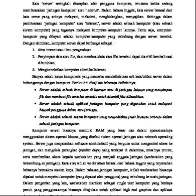
Description
5V ±1% Reference Oscillator Sync Terminal Internal Soft Start Deadtime Control Under Voltage Lockout
The KA3525A is a monolithic integrated circuit that includes all of the control circuits necessary for a pulse width modulating regulator. There are a voltage reference, an error amplifier, a pulse width modulator, an oscillator, an under voltage lockout, a soft start circuit, and the output driver in the chip. 16-DIP
1
Internal Block Diagram VC
13
VREF 16 BAND GAP REF 5V
VCC 15 GND
12
EA(-)
1
EA(+)
2
EAOUT
9
C (SOFT START)
U.V.L.O.
11
_
OUTPUT A
ERR AMP + _
LATCH
PWM COMP +
S
R
8
14 OUTPUT B
CT
5K
5
OSCILLATOR
F/F
10 SHUT DOWN
5K
Q Q
7 DISCHARGE
3 SYNC
6 RT
4 OSC OUTPUT
Rev. 1.0.1 ©2002 Fairchild Semiconductor Corporation
KA3525A
Absolute Maximum Ratings Parameter
Symbol
Value
Unit
VCC
40
V
Collector Supply Voltage
VC
40
V
Output Current, Sink or Source
IO
500
mA
IREF
50
mA
ICHG(OSC)
5
mA
Supply Voltage
Reference Output Current Oscillator Charging Current Power Dissipation (TA = 25°C)
PD
1000
m/W
Operating Temperature
TOPR
0 ~ +70
°C
Storage Temperature
TSTG
-65 ~ +150
°C
Lead Temperature (Soldering, 10sec)
TLEAD
+300
°C
Electrical Characteristics (VCC = 20V, TA = 0 to +70°C, unless otherwise specified) Parameter
Symbol
Conditions
Min.
Typ. Max.
Unit
5.0
5.1
5.2
V
REFERENCE SECTION Reference Output Voltage
VREF
TJ = 25°C
Line Regulation
∆VREF
VCC = 8 to 35V
-
9
20
mV
Load Regulation
∆VREF
IREF = 0 to 20mA
-
20
50
mV
VREF = 0, TJ = 25°C
-
80
100
mA
4.95
-
5.25
V
-
20
50
mV
TJ = 125°C ,1KHRS
-
20
50
mV
-
±3
±6
%
Short Circuit Output Current
ISC
Total Output Variation (Note1)
∆VREF
Temperature Stability (Note1)
STT
Long Term Stability (Note1)
ST
Line, Load and Temperature -
OSCILLATOR SECTION Initial Accuracy (Note1, 2)
ACCUR
TJ = 25°C
Frequency Change With Voltage
∆f/∆VCC
VCC = 8 to 35V (Note1, 2)
Maximum Frequency
f(MAX)
RT = 2kΩ, CT = 470pF
Minimum Frequency
f(MIN)
RT = 200kΩ, CT = 0.1uF
Clock Amplitude (Note1, 2)
V(CLK)
Clock Width (Note1, 2)
tW(CLK)
Sync Threshold Sync Input Current
2
TJ = 25°C -
VTH(SYNC) II(SYNC)
Sync = 3.5V
-
±0.8
±2
%
400
430
-
kHz
-
60
120
Hz
3
4
-
V
0.3
0.6
1
µs
1.2
2
2.8
V
-
1.3
2.5
mA
KA3525A
Electrical Characteristics (Continued) (VCC = 20V, TA = 0 to +70°C, unless otherwise specified) Parameter
Symbol
Conditions
Min.
VIO
-
-
IBIAS
-
IIO
-
Typ. Max. Unit
ERROR AMPLIFIER SECTION (VCM = 5.1V) Input Offset Voltage Input Bias Current Input Offset Current Open Loop Voltage Gain
GVO
1.5
10
mV
-
1
10
µA
-
0.1
1
µA
RL ≥ 10MΩ
60
80
-
dB
Common Mode Rejection Ratio
CMRR
VCM = 1.5 to 5.2V
60
90
-
dB
Power Supply Rejection Ratio
PSRR
VCC = 8 to 3.5V
50
60
-
dB
PWM COMPARATOR SECTION Minimum Duty Cycle
D(MIN)
-
-
-
0
%
Maximum Duty Cycle
D(MAX)
-
45
49
-
%
Input Threshold Voltage (Note2)
VTH1
Zero Duty Cycle
0.7
0.9
-
V
Input Threshold Voltage (Note2)
VTH2
Max Duty Cycle
-
3.2
3.6
V
ISOFT
VSD = 0V, VSS = 0V
25
51
80
µA
-
0.3
0.7
V
0.9
1.3
1.7
V
SOFT-START SECTION Soft Start Current Soft Start Low Level Voltage
VSL
Shutdown Threshold Voltage
VTH(SD)
Shutdown Input Current
VSD = 25V -
IN(SD)
VSD = 2.5V
-
0.3
1
mA
Low Output Voltage I
VOL I
ISINK = 20mA
-
0.1
0.4
V
Low Output Voltage II
VOL II
ISINK = 100mA
-
0.05
2
V
High Output Voltage I
VCH I
ISOURCE = 20mA
18
19
-
V
High Output Voltage II
VCH II
ISOURCE = 100mA
17
18
-
V
OUTPUT SECTION
Under Voltage Lockout
VUV
V8 and V9 = High
6
7
8
V
Collector Leakage Current
ILKG
VCC = 35V
-
80
200
µA
Rise Time (Note1)
tR
CL = 1uF, TJ = 25°C
-
80
600
ns
Fall Time (Note1)
tF
CL = 1uF, TJ = 25°C
-
70
300
ns
VCC = 35V
-
12
20
mA
STANDBY CURRENT Supply Current
ICC
Note : 1. These parameters. although guaranteed over the recommended operating conditions, are not 100% tested in production 2. Tested at fOSC=40kHz (RT =3.6K, CT =0.01uF, RI = 0Ω)
3
KA3525A
Test Circuit
16 3k
Vcc
BAND GAP REF 5V
15 0.1
RWM ADJ
U.V.L.O.
13
12
10k _
1
ERR AMP
2
1.5K
OUT A
_
LATCH S S R
ERR AMP
+
+
10K
SOFT START
A
11 10k
OSCILLATOR
9
0.01 +
VC
0.1
3 6
8
10k F/F
5.0uF
B
14
CLOCK
5.0k
10
OUT B
5.0k VREF
5.0k
7
5
SHUTDOWN CT
100 RAMP
DEAD TIME RT
0.001 + 0.009
0.1 3.6k
4
KA3525A
Mechanical Dimensions Package
16-DIP
#9
7.62 0.300
2.54 0.100
1.50 ±0.10 0.059 ±0.004
#8
0.46 ±0.10 0.018 ±0.004
#16
19.80 MAX 0.780
#1
19.40 ±0.20 0.764 ±0.008
(
0.81 ) 0.032
6.40 ±0.20 0.252 ±0.008
3.25 ±0.20 0.128 ±0.008
5.08 MAX 0.200
0.38 MIN 0.014
3.30 ±0.30 0.130 ±0.012
+0.10
0~15°
0.25 –0.05 +0.004
0.010 –0.002
5
KA3525A
Ordering Information Product Number
Package
Operating Temperature
KA3525A
16-DIP
0 ~ +70°C
DISCLAIMER FAIRCHILD SEMICONDUCTOR RESERVES THE RIGHT TO MAKE CHANGES WITHOUT FURTHER NOTICE TO ANY PRODUCTS HEREIN TO IMPROVE RELIABILITY, FUNCTION OR DESIGN. FAIRCHILD DOES NOT ASSUME ANY LIABILITY ARISING OUT OF THE APPLICATION OR USE OF ANY PRODUCT OR CIRCUIT DESCRIBED HEREIN; NEITHER DOES IT CONVEY ANY LICENSE UNDER ITS PATENT RIGHTS, NOR THE RIGHTS OF OTHERS. LIFE POLICY FAIRCHILD’S PRODUCTS ARE NOT AUTHORIZED FOR USE AS CRITICAL COMPONENTS IN LIFE DEVICES OR SYSTEMS WITHOUT THE EXPRESS WRITTEN APPROVAL OF THE PRESIDENT OF FAIRCHILD SEMICONDUCTOR CORPORATION. As used herein: 1. Life devices or systems are devices or systems which, (a) are intended for surgical implant into the body, or (b) or sustain life, and (c) whose failure to perform when properly used in accordance with instructions for use provided in the labeling, can be reasonably expected to result in a significant injury of the .
2. A critical component in any component of a life device or system whose failure to perform can be reasonably expected to cause the failure of the life device or system, or to affect its safety or effectiveness.
www.fairchildsemi.com 10/2/02 0.0m 001 Stock#DSxxxxxxxx 2002 Fairchild Semiconductor Corporation
KA3525A
SMPS Controller Features • • • • •
Description
5V ±1% Reference Oscillator Sync Terminal Internal Soft Start Deadtime Control Under Voltage Lockout
The KA3525A is a monolithic integrated circuit that includes all of the control circuits necessary for a pulse width modulating regulator. There are a voltage reference, an error amplifier, a pulse width modulator, an oscillator, an under voltage lockout, a soft start circuit, and the output driver in the chip. 16-DIP
1
Internal Block Diagram VC
13
VREF 16 BAND GAP REF 5V
VCC 15 GND
12
EA(-)
1
EA(+)
2
EAOUT
9
C (SOFT START)
U.V.L.O.
11
_
OUTPUT A
ERR AMP + _
LATCH
PWM COMP +
S
R
8
14 OUTPUT B
CT
5K
5
OSCILLATOR
F/F
10 SHUT DOWN
5K
Q Q
7 DISCHARGE
3 SYNC
6 RT
4 OSC OUTPUT
Rev. 1.0.1 ©2002 Fairchild Semiconductor Corporation
KA3525A
Absolute Maximum Ratings Parameter
Symbol
Value
Unit
VCC
40
V
Collector Supply Voltage
VC
40
V
Output Current, Sink or Source
IO
500
mA
IREF
50
mA
ICHG(OSC)
5
mA
Supply Voltage
Reference Output Current Oscillator Charging Current Power Dissipation (TA = 25°C)
PD
1000
m/W
Operating Temperature
TOPR
0 ~ +70
°C
Storage Temperature
TSTG
-65 ~ +150
°C
Lead Temperature (Soldering, 10sec)
TLEAD
+300
°C
Electrical Characteristics (VCC = 20V, TA = 0 to +70°C, unless otherwise specified) Parameter
Symbol
Conditions
Min.
Typ. Max.
Unit
5.0
5.1
5.2
V
REFERENCE SECTION Reference Output Voltage
VREF
TJ = 25°C
Line Regulation
∆VREF
VCC = 8 to 35V
-
9
20
mV
Load Regulation
∆VREF
IREF = 0 to 20mA
-
20
50
mV
VREF = 0, TJ = 25°C
-
80
100
mA
4.95
-
5.25
V
-
20
50
mV
TJ = 125°C ,1KHRS
-
20
50
mV
-
±3
±6
%
Short Circuit Output Current
ISC
Total Output Variation (Note1)
∆VREF
Temperature Stability (Note1)
STT
Long Term Stability (Note1)
ST
Line, Load and Temperature -
OSCILLATOR SECTION Initial Accuracy (Note1, 2)
ACCUR
TJ = 25°C
Frequency Change With Voltage
∆f/∆VCC
VCC = 8 to 35V (Note1, 2)
Maximum Frequency
f(MAX)
RT = 2kΩ, CT = 470pF
Minimum Frequency
f(MIN)
RT = 200kΩ, CT = 0.1uF
Clock Amplitude (Note1, 2)
V(CLK)
Clock Width (Note1, 2)
tW(CLK)
Sync Threshold Sync Input Current
2
TJ = 25°C -
VTH(SYNC) II(SYNC)
Sync = 3.5V
-
±0.8
±2
%
400
430
-
kHz
-
60
120
Hz
3
4
-
V
0.3
0.6
1
µs
1.2
2
2.8
V
-
1.3
2.5
mA
KA3525A
Electrical Characteristics (Continued) (VCC = 20V, TA = 0 to +70°C, unless otherwise specified) Parameter
Symbol
Conditions
Min.
VIO
-
-
IBIAS
-
IIO
-
Typ. Max. Unit
ERROR AMPLIFIER SECTION (VCM = 5.1V) Input Offset Voltage Input Bias Current Input Offset Current Open Loop Voltage Gain
GVO
1.5
10
mV
-
1
10
µA
-
0.1
1
µA
RL ≥ 10MΩ
60
80
-
dB
Common Mode Rejection Ratio
CMRR
VCM = 1.5 to 5.2V
60
90
-
dB
Power Supply Rejection Ratio
PSRR
VCC = 8 to 3.5V
50
60
-
dB
PWM COMPARATOR SECTION Minimum Duty Cycle
D(MIN)
-
-
-
0
%
Maximum Duty Cycle
D(MAX)
-
45
49
-
%
Input Threshold Voltage (Note2)
VTH1
Zero Duty Cycle
0.7
0.9
-
V
Input Threshold Voltage (Note2)
VTH2
Max Duty Cycle
-
3.2
3.6
V
ISOFT
VSD = 0V, VSS = 0V
25
51
80
µA
-
0.3
0.7
V
0.9
1.3
1.7
V
SOFT-START SECTION Soft Start Current Soft Start Low Level Voltage
VSL
Shutdown Threshold Voltage
VTH(SD)
Shutdown Input Current
VSD = 25V -
IN(SD)
VSD = 2.5V
-
0.3
1
mA
Low Output Voltage I
VOL I
ISINK = 20mA
-
0.1
0.4
V
Low Output Voltage II
VOL II
ISINK = 100mA
-
0.05
2
V
High Output Voltage I
VCH I
ISOURCE = 20mA
18
19
-
V
High Output Voltage II
VCH II
ISOURCE = 100mA
17
18
-
V
OUTPUT SECTION
Under Voltage Lockout
VUV
V8 and V9 = High
6
7
8
V
Collector Leakage Current
ILKG
VCC = 35V
-
80
200
µA
Rise Time (Note1)
tR
CL = 1uF, TJ = 25°C
-
80
600
ns
Fall Time (Note1)
tF
CL = 1uF, TJ = 25°C
-
70
300
ns
VCC = 35V
-
12
20
mA
STANDBY CURRENT Supply Current
ICC
Note : 1. These parameters. although guaranteed over the recommended operating conditions, are not 100% tested in production 2. Tested at fOSC=40kHz (RT =3.6K, CT =0.01uF, RI = 0Ω)
3
KA3525A
Test Circuit
16 3k
Vcc
BAND GAP REF 5V
15 0.1
RWM ADJ
U.V.L.O.
13
12
10k _
1
ERR AMP
2
1.5K
OUT A
_
LATCH S S R
ERR AMP
+
+
10K
SOFT START
A
11 10k
OSCILLATOR
9
0.01 +
VC
0.1
3 6
8
10k F/F
5.0uF
B
14
CLOCK
5.0k
10
OUT B
5.0k VREF
5.0k
7
5
SHUTDOWN CT
100 RAMP
DEAD TIME RT
0.001 + 0.009
0.1 3.6k
4
KA3525A
Mechanical Dimensions Package
16-DIP
#9
7.62 0.300
2.54 0.100
1.50 ±0.10 0.059 ±0.004
#8
0.46 ±0.10 0.018 ±0.004
#16
19.80 MAX 0.780
#1
19.40 ±0.20 0.764 ±0.008
(
0.81 ) 0.032
6.40 ±0.20 0.252 ±0.008
3.25 ±0.20 0.128 ±0.008
5.08 MAX 0.200
0.38 MIN 0.014
3.30 ±0.30 0.130 ±0.012
+0.10
0~15°
0.25 –0.05 +0.004
0.010 –0.002
5
KA3525A
Ordering Information Product Number
Package
Operating Temperature
KA3525A
16-DIP
0 ~ +70°C
DISCLAIMER FAIRCHILD SEMICONDUCTOR RESERVES THE RIGHT TO MAKE CHANGES WITHOUT FURTHER NOTICE TO ANY PRODUCTS HEREIN TO IMPROVE RELIABILITY, FUNCTION OR DESIGN. FAIRCHILD DOES NOT ASSUME ANY LIABILITY ARISING OUT OF THE APPLICATION OR USE OF ANY PRODUCT OR CIRCUIT DESCRIBED HEREIN; NEITHER DOES IT CONVEY ANY LICENSE UNDER ITS PATENT RIGHTS, NOR THE RIGHTS OF OTHERS. LIFE POLICY FAIRCHILD’S PRODUCTS ARE NOT AUTHORIZED FOR USE AS CRITICAL COMPONENTS IN LIFE DEVICES OR SYSTEMS WITHOUT THE EXPRESS WRITTEN APPROVAL OF THE PRESIDENT OF FAIRCHILD SEMICONDUCTOR CORPORATION. As used herein: 1. Life devices or systems are devices or systems which, (a) are intended for surgical implant into the body, or (b) or sustain life, and (c) whose failure to perform when properly used in accordance with instructions for use provided in the labeling, can be reasonably expected to result in a significant injury of the .
2. A critical component in any component of a life device or system whose failure to perform can be reasonably expected to cause the failure of the life device or system, or to affect its safety or effectiveness.
www.fairchildsemi.com 10/2/02 0.0m 001 Stock#DSxxxxxxxx 2002 Fairchild Semiconductor Corporation
Related Documents 3h463d

Ka3525 Pwm Ic 3g5f3b
March 2023 0
Calcular Frecuencia Del Oscilador Del Pwm Ka3525 4d3t
June 2022 0
Pwm Ic For Smps Introductionob2263.pdf 5n3el
December 2021 0
Pwm n613g
April 2020 27
Pwm n613g
December 2019 66
Pwm 251g36
April 2020 23More Documents from "Sunarto" 2g6x45
Ka3525 Pwm Ic 3g5f3b
March 2023 0
Lumion 7 Crack Cgpersia 4i4jm
April 2023 0
Job+sheet+tad 2t205m
September 2020 0
Penguat+audio 1t3dj
September 2020 0
Job+sheet+tal 6r3n5b
September 2020 0