Porter Governor 4i5d1t
This document was ed by and they confirmed that they have the permission to share it. If you are author or own the copyright of this book, please report to us by using this report form. Report 3i3n4
Overview 26281t
& View Porter Governor as PDF for free.
More details 6y5l6z
- Words: 1,057
- Pages: 4
EXPERIMENT 2
PORTER GOVERNOR AIM: To determine the controlling force, friction force and effort of governor and to draw the characteristic curves. THEORY: The function of a governor is to maintain the speed of an engine within specified limits whenever there is a variation of load. It maintains speed within set limits from no load on the engine to full rated load on the engine. If a governor is to regulate satisfactorily it must posses certain fundamental qualities. In the first instance a governor must be so designed that the engine can develop maximum power when the sleeve reaches the bottom of its travel. Further if the engine load is suddenly removed, the sleeve must reach the top of its travel before the speed is excessively increased. Under normal running conditions this sleeve should float steadily in a mean position between these extreme limits i.e., the governor must be stable. In addition, it must be sensitive, i.e., it must respond readily to speed change. Lastly, it must be capable of exerting sufficient effort at the sleeve to operate the control mechanism.
Porter Governor Controlling Force: The constraining forces, which control the movement of the balls in a centrifugal governor, in whatever manner they may be applied, can be regarded as equivalent to a single inward radially force F acting at the center of each ball. This force F is called the Controlling Force.
Figure shows a gravity controlled centrifugal governor of the conical pendulum type known as porter governor. The arms AB of equal length and carrying equal masses at B are pivoted to the upper end of the vertical spindle DE. The sleeve S, carrying a heavy load W, and free to slide on the spindle, is connected to the arm AB by equal links BC, arranged symmetrically as shown. The spindle is driven by the engine and as the speed rises the masses fly outwards, giving upward motion to the sleeve. This movement is transmitted through the link-mechanism FGH to the throttle valve or cut-off device (F being fixed pivot) and so regulates the engine power. PROCEDURE: 1. Mount the porter Governor assembly over the spindle. 2. Start the motor & adjust the speed to the required speed value. 3. When the speed increases due to centrifugal effect, the sleeve will rise. 4. Note the speed for the required sleeve rise. 5. Measure the speed for different sleeve rise. 6. Repeat the experiment with different for loads.
1. = Sin-1 [C1 / L] 2. Theoretical Height hth = {(Wb + Ws) / mb} x 91.2 / N2 in m 3. Experimental height, hex = r tan in m 4. Frictional Force, f = {mb h N2 / 91.2} - (Wb + Ws) in N 5. Controlling force, Fc = mb (n) 2 r in N 6. Effort, Q = 0.01 (mb + M) x g in N 7. Power required to lift the sleeve P = Effort x Sleeve lift = Q * x Watt SPECIMEN CALCULATION: GRAPHS: 1. Sleeve lift vs. Governor Speed 2. Height of Governor Vs Governor Speed 3. Radius of rotation Vs Controlling Force
AIM:-TO PERFORM EXPERIMENT ON WATT AND PORTER GOVERNORS TO PREPARE PERFORMANCE CHARACTERISTIC CURVES, AND TO FIND STABILITY & SENSITIVITY.
APPARATUS USED: - WATT AND PORTER GOVERNORS. INTRODUCTION & THEORY: - THE FUNCTION OF A GOVERNOR IS TO REGULATE THE MEAN SPEED OF AN ENGINE, WHEN THERE ARE VARIATIONS IN THE LOAD E.G. WHEN THE LOAD ON AN ENGINE INCREASES, ITS SPEED DECREASES, THEREFORE IT BECOMES NECESSARY TO INCREASE THE SUPPLY OF WORKING FLUID. WHEN THE LOAD ON THE ENGINE DECREASES, ITS SPEED INCREASES AND THUS LESS WORKING FLUID IS REQUIRED. THE GOVERNOR AUTOMATICALLY CONTROLS THE SUPPLY OF WORKING FLUID TO THE ENGINE WITH THE VARYING LOAD CONDITIONS AND KEEPS THE MEAN SPEED WITHIN CERTAIN LIMITS. THE GOVERNORS MAY, BROADLY, BE CLASSIFIED AS 1. CENTRIFUGAL GOVERNOR 2. INERTIA GOVERNOR THE CENTRIFUGAL GOVERNORS MAY FURTHER BE CLASSIFIED AS FOLLOWS: 1. PENDULUM TYPE (WATT GOVERNOR) 2. LOADED TYPE (I) DEAD WEIGHT GOVERNOR (PORTER GOVERNOR AND PROELL GOVERNOR) (II) SPRING CONTROLLED GOVERNORS (HARTNELL GOVERNOR, HARTUNG GOVERNOR, WILSON-HARTNELL GOVERNOR AND PICKERING GOVERNOR. WATT GOVERNOR: - THE SIMPLEST FORM OF A CENTRIFUGAL GOVERNOR IS A WATT GOVERNOR. IT IS BASICALLY A CONICAL PENDULUM WITH LINKS ATTACHED TO A SLEEVE OF NEGLIGIBLE MASS. THE ARMS OF THE GOVERNOR MAY BE CONNECTED TO THE SPINDLE IN THE FOLLOWING THREE WAYS: 1. THE PIVOT P MAY BE ON THE SPINDLE AXIS. 2. THE PIVOT P MAY BE OFFSET FROM THE SPINDLE AXIS AND THE ARMS WHEN PRODUCED INTERSECT AT O. 3. THE PIVOT P MAY BE OFFSET, BUT THE ARMS CROSSES THE AXIS AT O. PORTER GOVERNOR: - THE PORTER GOVERNOR IS A MODIFICATION OF A WATT’S GOVERNOR, WITH CENTRAL LOAD ATTACHED TO THE SLEEVE. THE LOAD MOVES UP DOWN THE CENTRAL SPINDLE. THIS ADDITIONAL DOWNWARD FORCE INCREASES THE SPEED OF REVOLUTION REQUIRED TO ENABLE THE BALLS TO RISE TO ANY TO ANY PRE-DETERMINED LEVEL. OBSERVATION :· MASS OF THE BALL (M) = ————-KG. · WEIGHT OF THE BALL (W)=————NEWTONS · HEIGHT OF THE GOVERNOR (H) = ——- METRES · MINIMUM EQUILIBRIUM SPEED (N1) = —— R.P.M. · MINIMUM EQUILIBRIUM SPEED (N2) = —— R.P.M. · FRICTIONAL FORCE (F) = ————- NEWTONS · MEAN EQUILIBRIUM SPEED (N) = (N1 + N2)/2 IN R.P.M · MASS OF THE CENTRAL LOAD = ———KG. · WEIGHT OF THE CENTRAL LOAD (W) = ——–N · ANGLE OF INCLINATION OF THE ARM TO THE VERTICAL (Α ) = —— · ANGLE OF INCLINATION OF THE LINK TO THE VERTICAL (Β ) = —— CALCULATION:N2 = 895/H (FOR WATT GOVERNOR) N2 = ((M + M (1+Q)/2)/M) X (895/H) (FOR PORTER GOVERNOR ), WHERE, Q = TAN Β/ TAN Α SENSITIVENESS OF THE GOVERNOR = 2(N1 – N2)/ N1 + N2 = 2 (Ω2 – Ω1)/ Ω2 + Ω1 A GOVERNOR IS SAID TO BE STABLE WHEN FOR EVERY SPEED WITHIN THE WORKING RANGE THERE IS A DEFINITE CONFIGURATION I.E; THERE IS ONLY ONE RADIUS OF ROTATION OF THE GOVERNOR BALLS AT WHICH THE GOVERNOR IS IN EQUILIBRIUM. FOR A STABLE GOVERNOR, IF THE EQUILIBRIUM SPEED INCREASES, THE RADIUS OF GOVERNOR BALLS MUST ALSO INCREASE.
PORTER GOVERNOR (WITH WEIGHT) LENGTH OF EACH LINK L = 120MM INITIAL HEIGHT OF GOVERNOR H0=110MM INITIAL RADIUS OF ROTATION RO=135MM WEIGHT OF BALLS+ SLEEVE W=1+1.8 KG=2.8KG
Related Documents 3h463d

Porter Governor 4i5d1t
December 2019 59
Porter Governor 4i5d1t
November 2019 38
Porter Governor Mechanism 1c4q5q
December 2019 42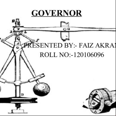
Governor 4l4z61
April 2022 0
Watt Governor 373644
December 2019 58
Governor Modes Of Operation 4t3k5s
December 2020 0More Documents from "C V CHANDRASHEKARA" 67584a
Porter Governor 4i5d1t
December 2019 59
Nimulid Md 4x4a22
November 2019 68
Fundamentals Of Vibrations Leonard Meirovitch 4g112a
November 2019 95
Ejemplos De Comentario De Textos d2b20
July 2021 0
Informe De Visita A Ladrillera Artesanal.docx 4m1h4r
December 2019 46