Transmission Towers 4m605y
This document was ed by and they confirmed that they have the permission to share it. If you are author or own the copyright of this book, please report to us by using this report form. Report 3i3n4
Overview 26281t
& View Transmission Towers as PDF for free.
More details 6y5l6z
- Words: 406
- Pages: 7
Electrical Transmission Tower : The main ing unit of overhead transmission line is transmission tower. Transmission towers have to carry the heavy transmission conductor at a sufficient safe height from ground. In addition to that all towers have to sustain all kinds of natural calamities.
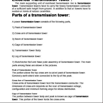
Parts of a transmission tower: A power transmission tower consists of the following parts, 1) Peak of transmission tower 2) Cross arm of transmission tower 3) Boom of transmission tower 4) Cage of transmission tower 5) Transmission Tower Body 6) Leg of transmission tower 7) Stub/Anchor Bolt and Base plate assembly of transmission tower. The main parts among these are shown in the pictures. Peak of Transmission Tower
The portion above the top cross arm is called peak of transmission tower. Generally earth shield wire connected to the tip of this peak. Cross Arm of Transmission Tower
Cross arms of transmission tower hold the transmission conductor. The dimension of cross arm depends on the level of transmission voltage, configuration and minimum forming angle for stress distribution. Cage of Transmission Tower
The portion between tower body and peak is known as cage of transmission tower. This portion of the tower holds the cross arms.
Transmission Tower Body
The portion from bottom cross arms up to the ground level is called transmission tower body. This portion of the tower plays a vital role for maintaining required ground clearance of the bottom conductor of the transmission line.
Types of Transmission Tower:
According to different considerations, there are different types of transmission towers. The transmission line goes as per available corridors. Due to unavailability of shortest distance straight corridor transmission line has to deviate from its straight way when obstruction comes. In total length of a long transmission line there may be several deviation points. According to the angle of deviation there are four types of transmission tower1. A – type tower – angle of deviation 0o to 2o. 2. B – type tower – angle of deviation 2o to 15o. 3. C – type tower – angle of deviation 15o to 30o. 4. D – type tower – angle of deviation 30o to 60o. Based on numbers of circuits carried by a transmission tower, it can be classisfied as-
1.Single circuit tower: A single circuit configuration has three conductors for the three phases.
2. Double circuit tower: While a double circuit configuration has six conductors (three phases for each circuit).
3. Multi circuit tower.
Related Documents 3h463d
Transmission Towers 4m605y
December 2019 53
Manual On Transmission Line Towers 5q245l
November 2019 86
Transmission Towers Foundation Design Book 5t6w23
November 2021 0
Design Of Stub For Transmission Line Towers 23122m
November 2019 105
Towers Perrin 451v4q
November 2019 63
Cooling Towers 6j725s
August 2021 0More Documents from "Aamir Shah" 57525f
Transmission Towers 4m605y
December 2019 53
T S Eliot As A Modern Poet 6a2f45
November 2019 97
A Comparative Guide To Anti-money Laundering 2o2v34
January 2021 0
Asm Fm 11th Edition 583i3g
October 2019 149
Difference Between ing And Auditing 3t94i
October 2022 0