Catia V5r17 Mold Design k5b6p
This document was ed by and they confirmed that they have the permission to share it. If you are author or own the copyright of this book, please report to us by using this report form. Report 3i3n4
Overview 26281t
& View Catia V5r17 Mold Design as PDF for free.
More details 6y5l6z
- Words: 4,212
- Pages: 61
Mold Tooling Design
CATIA Training Foils
Copyright DASSAULT SYSTEMES
Mold Tooling Design
Instructor Notes:
Copyright DASSAULT SYSTEMES
Version 5 Release 17 September 2006 EDU-CAT-EN-MTD-FI-V5R17
Mold Tooling Design
Course Presentation Objectives of the course In this course you will learn how to use workbench Mold Tooling Design to create a Plastic Injection Mold
Targeted audience New Mold Tooling Design s
1 day
Prerequisites
Copyright DASSAULT SYSTEMES
CATIA V5 Fundamentals TG1 Tooling Design Fundamentals
Instructor Notes:
Copyright DASSAULT SYSTEMES
Mold Tooling Design
Planning
Day 1 1. Introduction to Mold Tooling Design 2. Creating a New Mold 3. Editing the Mold Base
Exercises
Master exercise: Phone Handset step 1
AFTERNOON
5. 6. 7. 8.
Exercises
Master exercise: Phone Handset steps 2 and 3 Additional Exercise : the Cover
Copyright DASSAULT SYSTEMES
MORNING
Instructor Notes:
Copyright DASSAULT SYSTEMES
Working with Mold Components Mold Design to Manufacturing Creating Injection Features Additional Information
Mold Tooling Design
Table of Contents (1) 1. Introduction to Mold Tooling Design Accessing the Workbench Interface Presentation Mold Tooling Design Functions Mold Tooling Design Catalogs Settings Mold Creation : General Process
2. Creating a New Mold
Creating a New Mold Product Inserting the Molded Part Structure of the Molded Part Creating the Mold Base Defining a Stripper Plate Creating the Mold Base before the Molded Part Positioning the Molded Part
Copyright DASSAULT SYSTEMES
3. Editing the Mold Base
Editing the Definition of the Existing Mold Base Adding a Plate Splitting Core and Cavity Plates
Instructor Notes:
Copyright DASSAULT SYSTEMES
6
7 8 9 11 12 14
15
16 17 18 21 25 26 27
29
30 32 33
Mold Tooling Design
Table of Contents (2) 4. Working with Mold Components
Tooling Components : Generic (TG1) / Mold (MTD) Defining a Mold Component Instantiating a Mold Component Editing a Mold Component Specific Components : Inserts and Sliders Advanced Add/Remove Capabilities Managing Components
5. Mold Design to Manufacturing
Copyright DASSAULT SYSTEMES
Mold Components Drillings : Technological results Mold Components Drillings : Explode Holes Technological Results vs. Explode Holes
35
36 37 38 39 40 41 42
43 44 45 46
6. Creating Injection Features
48
Creating a Gate Creating a Runner Creating a Coolant Channel
49 52 53
7. Additional Information Analyzing Contextual Links in Assembly Structure Customizing the Bill of Material of a Mold Working with Large Assemblies : Cache Management
Instructor Notes:
Copyright DASSAULT SYSTEMES
57 58 59 60
Mold Tooling Design
Introduction to Mold Tooling Design You will discover CATIA V5 Mold Tooling Design interface and you will review the general process to create a Mold
Copyright DASSAULT SYSTEMES
Accessing the Workbench Interface Presentation Mold Tooling Design Functions Mold Tooling Design Catalogs Settings Mold Creation : General Process Description
Instructor Notes:
Copyright DASSAULT SYSTEMES
Mold Tooling Design
Accessing the Workbench
Copyright DASSAULT SYSTEMES
Workbench Mold Tooling Design is a member of the family of Mechanical Design applications (P2) :
Instructor Notes:
Copyright DASSAULT SYSTEMES
Mold Tooling Design
Interface Presentation Once inside workbench Mold Tooling Design, you have access to : • Dedicated Mold Tooling Design tools • General Assembly-level tools • Standard tools
Copyright DASSAULT SYSTEMES
Standard Tools
Instructor Notes:
Copyright DASSAULT SYSTEMES
MTD Tools
General Assembly Tools
Mold Tooling Design
Mold Tooling Design Functions (1)
New Mold Base
Add Slider Add Retainers
Add Mold Plate Add Insert Mold Base Elements
Guiding Components
Add Leader Pin Add Bushing Add Sleeve
Locating Components
Add Locating Ring Add Dowel Pin
Copyright DASSAULT SYSTEMES
Cap Screw Fixing Components
Instructor Notes:
Copyright DASSAULT SYSTEMES
Countersunk Screw Locking Screw
Mold Tooling Design
Mold Tooling Design Functions (2) Ejector Pin Ejector Ejection Components
Flat Ejector Ejector Sleeve Sprue Bushing
Injection Components
Core Pin Sprue Puller Stop Pin
Injection Feature : Gate
Pillar
Injection Feature : Runner
O-Ring
Coolant Channel
Plug Baffle
Copyright DASSAULT SYSTEMES
Miscellaneous Components
Instructor Notes:
Copyright DASSAULT SYSTEMES
Component Eye Bolt Spring
Angle Pin Knockout Pin
Mold Tooling Design
Mold Tooling Design Catalogs For Mold Bases and components, the catalogues of major market providers are available :
Copyright DASSAULT SYSTEMES
Creation of a new Mold Base
Creation of a new component (e.g. Leader Pin)
Instructor Notes:
Copyright DASSAULT SYSTEMES
Mold Tooling Design
Settings : Specific Mold Tooling Design Settings
Copyright DASSAULT SYSTEMES
Identical to capabilities available in application Tooling Design (TG1)
Instructor Notes:
Copyright DASSAULT SYSTEMES
Mold Tooling Design
Settings : Recommended General Settings
Copyright DASSAULT SYSTEMES
Identical to recommendations available for application Tooling Design (TG1)
Instructor Notes:
Copyright DASSAULT SYSTEMES
Mold Tooling Design
Mold Creation : General Process
Define a Mold Base
From a Molded Part
Adjust position of the Molded Part
Copyright DASSAULT SYSTEMES
Add components
Add injection runners and coolant channels
Instructor Notes:
Copyright DASSAULT SYSTEMES
Core and Cavity separation
End of Mold creation
Mold Tooling Design
Creating a new Mold You will see how to create a new Mold Product from scratch, insert the Molded Part in the new Product and create the corresponding Mold Base.
Copyright DASSAULT SYSTEMES
Creating a new Mold Product Inserting the Molded Part Structure of the Molded Part Creating the Mold Base Positioning the Molded Part
Instructor Notes:
Copyright DASSAULT SYSTEMES
Mold Tooling Design
Creating a new Mold Product A Mold Product is a standard CATIA V5 Product where specific Mold elements will be inserted later :
You can create a new CATIA V5 product by : Starting workbench Mold Tooling Design :
Or explicitly creating a new Product :
Copyright DASSAULT SYSTEMES
A new Product is created
Instructor Notes:
Copyright DASSAULT SYSTEMES
Mold Tooling Design
Inserting the Molded Part in the Mold Product The Molded Part can be inserted in the Mold Assembly by inserting the already existing CATPart :
Copyright DASSAULT SYSTEMES
From the contextual menu of the top Product : Components / Existing Component, then selecting the name of the CATPart file Or by using standard menu Insert / Existing Component… , then selecting the name of the CATPart file
Instructor Notes:
Copyright DASSAULT SYSTEMES
The Molded Part is inserted in the Product
Mold Tooling Design
Structure of the Molded Part (1) : Requirements Its Part Number (see tab Product in contextual menu Properties) must be MoldedPart
Copyright DASSAULT SYSTEMES
You can define as you wish the Instance name and the name of the CATPart file
Instructor Notes:
Copyright DASSAULT SYSTEMES
Mold Tooling Design
Structure of the Molded Part (2) : Requirements The Molded Part must contain the part itself and also all the surface elements required for core/cavity separation. It is generally created as the result of the preparation work done in workbench Core & Cavity Design or Generative Shape Design.
Copyright DASSAULT SYSTEMES
It is recommended that the defines the following elements in the Molded Part, in an open body called PartingBody : PartingSurface : the external parting surface around the Molded Part, created from the parting line CoreSurface : of the core side of the part (including fills of functional holes) and of PartingSurface CavitySurface : of the cavity side of the part (including fills of functional holes) and of PartingSurface The elements bearing these names will be used by the application as (editable) default elements for core/cavity split operations and for creating gates and runners. If they are not present, you will have to explicitly select other elements in the Molded Part when performing core/cavity split operations.
Instructor Notes:
Copyright DASSAULT SYSTEMES
Mold Tooling Design
Structure of the Molded Part (3) : Example PartingSurface
The Core Side may come from any operation (CCV Define Pulling direction, GSD Extract, …)
Core Side Cavity Side
Filling Holes
Copyright DASSAULT SYSTEMES
Filling Holes may come from any filling operation done in GSD or CCV
Instructor Notes:
Copyright DASSAULT SYSTEMES
CoreSurface = PartingSurface + Core Side + Filling Holes CavitySurface = PartingSurface + Cavity side + Filling Holes
Mold Tooling Design
Creating the Mold Base (1) You can define a new Mold Base by :
Copyright DASSAULT SYSTEMES
Defining entirely the set of plates with their dimensions Or selecting an existing Mold Base in a catalog
Instructor Notes:
Copyright DASSAULT SYSTEMES
Mold Tooling Design
Creating the Mold Base (2) You can create a new Mold Base by defining entirely the number, types and dimensions of the plates : The default Mold Base configuration includes most of the predefined types of plates, with default values for their dimensions. You may deactivate some of them (except Core and Cavity, which are mandatory), or modify each dimension depending on your design needs.
Copyright DASSAULT SYSTEMES
Function Create a new Mold allows you to create a new Mold Base
Instructor Notes:
Copyright DASSAULT SYSTEMES
• Mandatory plates are shaded in the and cannot be deactivated • Optional plates can be deactivated : the preview of the Mold Base is then automatically updated
Mold Base dialog Box lets you control the definition of the plates to include in the Mold Base
Mold Tooling Design
Creating the Mold Base (3) You can also select an existing Mold Base variant in a catalog 1
3
2
Catalog Browser When you select a Mold Base variant, its dimensions (Length and Width) are previewed
You have access to the catalogs of many major market providers
4
Copyright DASSAULT SYSTEMES
5
The new Mold Base is created as a new Product inside the top Product
Instructor Notes:
Copyright DASSAULT SYSTEMES
Once you have selected your Mold Base, a full preview is displayed
Mold Tooling Design
Creating the Mold Base (4) Structure of the resulting Mold Product Once the Mold Base has been created, the overall structure of the Mold Product is made up of : A top Product containing the two following elements A Component corresponding to the Molded Part Another Product corresponding to the Mold tool assembly itself, containing the Mold Base plates. Other components will be later inserted in this assembly. This Product is structured into 3 main sub-assemblies, defined as Products: InjectionSide, EjectionSide and EjectorSystem
Top Product Component Molded Part
Copyright DASSAULT SYSTEMES
Mold Base product
Instructor Notes:
Copyright DASSAULT SYSTEMES
Sub-products
Mold Tooling Design
Creating the Mold Base : Defining a Stripper Plate Using a Stripper Plate When the Molded Part contains deep hollows, you may decide not to use Ejectors, but instead a Stripper Plate to avoid creating marks on the Part.
Creating a Stripper Plate :
Copyright DASSAULT SYSTEMES
You can select it when creating the Mold Base, or add it later using function Add Mold Plate The Stripper Plate is located on top of the Core Plate, in sub-product Ejection System. Its overlap with the Core Plate can be adjusted. Its shape to fit the Molded Part can be adjusted through Split Component… operation, similar to what is done on Core or Cavity Plates.
Instructor Notes:
Copyright DASSAULT SYSTEMES
Mold Tooling Design
Creating the Mold Base : Creating it before the Molded Part Creation of the Molded Part :
Copyright DASSAULT SYSTEMES
If the Mold Base is created prior to inserting the existing CATPart file corresponding to the Molded Part, a new empty Component named MoldedPart will be automatically created by application Mold Tooling Design This component can then be interactively completed, using standard Part Design, Core&Cavity Design, Generative Shape Design and Assembly Design functions
It can also be further replaced, using contextual menu function Components… / Replace Component
Instructor Notes:
Copyright DASSAULT SYSTEMES
Mold Tooling Design
Positioning the Molded Part : Automatic Positioning When the Mold Base Product is created, it is automatically positioned with regard to the Axis System defined as active in the Molded Part : First, the reference Axis System of the Mold Base (located at the bottom of the Core Plate) is snapped onto the active Axis System of the Molded Part. Then the Mold Base position is adjusted along Z in order to position the origin of the Molded Part at medium distance between the top of the Cavity Plate and the bottom of the Core Plate Core Plate and Cavity Plate are in overlap
Extreme sides of the Cavity Plate (top) and Core Plate (bottom)
Copyright DASSAULT SYSTEMES
Active Axis System of the Molded Part (yellow)
If there is no active Axis System in the Molded Part, the system uses the default origin and standard planes of the Part.
Instructor Notes:
Copyright DASSAULT SYSTEMES
Axis System of the Mold Base (pink)
Mold Tooling Design
Positioning the Molded Part : Additional capabilities
You can also use function Snap to put in coincidence any axis system of the Molded Part with any axis system of the Mold Base. You can also use main planes for snapping purposes.
Copyright DASSAULT SYSTEMES
You can also use the Com to dynamically move the Molded Part in order to ensure that the Parting Surface will fully split Core and Cavity plates, or to define precise location values. You can for example snap the Com to the local axis system of the Molded Part or to the Parting Surface, in order to drag it as desired.
You can also use function Manipulation to position the Part
Instructor Notes:
Copyright DASSAULT SYSTEMES
Mold Tooling Design
Editing the Mold Base You will see how to edit the definition of a Mold Base.
Copyright DASSAULT SYSTEMES
Editing the Definition of the Existing Mold Base Adding a Plate Splitting Core and Cavity Plates
Instructor Notes:
Copyright DASSAULT SYSTEMES
Mold Tooling Design
Editing the Definition of the Existing Mold Base (1) It is possible to update in various ways the definition of the current Mold Base by using contextual menu function Edit Mold. The Mold Base preview is automatically updated when you make a modification. You can select another Mold Base reference in the Catalog
Copyright DASSAULT SYSTEMES
You can browse the Design Table containing the list of Mold Base variants and select a new one
Instructor Notes:
Copyright DASSAULT SYSTEMES
Mold Tooling Design
Editing the Definition of the Existing Mold Base (2) In menu Edit Mold, it is also possible to : Update the dimension of some plates (either mandatory like CorePlate, or optional ones, like the CorePlate)
Copyright DASSAULT SYSTEMES
Remove optional plates by unselecting them in the
Instructor Notes:
Copyright DASSAULT SYSTEMES
Mold Tooling Design
Adding a Plate It is possible to add a plate inside an existing Mold Base. The new plate must be of one of the available predefined types allowed for the current Mold Base. Current limitation : it is not possible to add other types of plates (defined types of plates)
The Mold Base preview is updated with the selected plate
Copyright DASSAULT SYSTEMES
Only types allowed for the current Mold Base are displayed
Note that it is not possible to modify parameters which are related to the overall size of the Mold Base
Instructor Notes:
Copyright DASSAULT SYSTEMES
Once created, the new plate is inserted in the tree structure
Mold Tooling Design
Splitting Core and Cavity Plates Core and Cavity Plates can be split to fit the shape of the Molded Part. This operation leads to a contextual dependency of Core and Cavity Plates with respect to the Molded Part. Automatic context management is performed by application MTD (Part Interface mechanism) in the same way as it is done in the case of Component drillings (see further).
Copyright DASSAULT SYSTEMES
For both Core and Cavity plates, there is a dedicated function Split Component… in their contextual menu.
The application will use by default as splitting surface the one named CoreSurface (resp. CavitySurface), if present in the Molded Part. You can select another surface if you wish.
Instructor Notes:
Copyright DASSAULT SYSTEMES
Product Interface TlgItf_InjectionSide is comprised of Part Interface Product1_InjectionSide containing a Published Copy of CavitySurface from the MoldedPart
Mold Tooling Design
Exercise Presentation And now practice on Step 1 of the Master Exercise, to learn about :
Copyright DASSAULT SYSTEMES
Creating a new Mold Product Defining the Molded Part Selecting a Mold Base Adjusting the position of the Molded Part Splitting Core and Cavity Plates
Instructor Notes:
Copyright DASSAULT SYSTEMES
Mold Tooling Design
Working with Mold Components You will learn how to manage Mold Tooling Components.
Copyright DASSAULT SYSTEMES
Tooling Components : Generic (TG1) / Mold (MTD) Defining a Mold Component Instantiating a Mold Component Editing a Mold Component Specific Components : Inserts and Sliders Advanced Add/Remove Capabilities Managing Components
Instructor Notes:
Copyright DASSAULT SYSTEMES
Mold Tooling Design
Tooling Components : Generic (TG1) / Mold (MTD) Workbenches Tooling Design (TG1) and Mold Tooling Design (MTD) share the same Tooling Component concept. All information and behaviors described in the TG1 training course about Components are also relevant for MTD. However, workbench MTD contains : Additional predefined types of Components compared to TG1 : Locating Ring, Sprue Bushing, Sprue Puller, O-Ring, Plug, Baffle
Copyright DASSAULT SYSTEMES
Standard market providers’ catalogs for most of the Components for which only Part or Product samples are available in TG1 : Leader Pin, Bushing, Sleeve, Ejector Pin, Ejector, Flat Ejector, Ejector Sleeve, Core Pin, Stop Pin, Angle Pin, Knock-out, Pillar, Eye Bolt
Instructor Notes:
Copyright DASSAULT SYSTEMES
Mold Tooling Design
Defining a Mold Component
Copyright DASSAULT SYSTEMES
Identical to the definition of a Tooling Design (TG1) Component
Instructor Notes:
Copyright DASSAULT SYSTEMES
Mold Tooling Design
Instantiating a Component
Copyright DASSAULT SYSTEMES
Identical to capabilities available in application Tooling Design (TG1)
Instructor Notes:
Copyright DASSAULT SYSTEMES
Mold Tooling Design
Editing a Component
Copyright DASSAULT SYSTEMES
Identical to capabilities available in application Tooling Design (TG1)
Instructor Notes:
Copyright DASSAULT SYSTEMES
Mold Tooling Design
Specific Components : Inserts and Sliders
Copyright DASSAULT SYSTEMES
Identical to capabilities available in application Tooling Design (TG1)
Instructor Notes:
Copyright DASSAULT SYSTEMES
Mold Tooling Design
Advanced Add/Remove Capabilities
Copyright DASSAULT SYSTEMES
Identical to capabilities available in application Tooling Design (TG1)
Instructor Notes:
Copyright DASSAULT SYSTEMES
Mold Tooling Design
Managing Components
Copyright DASSAULT SYSTEMES
Identical to capabilities available in application Tooling Design (TG1)
Instructor Notes:
Copyright DASSAULT SYSTEMES
Mold Tooling Design
Mold Design to Manufacturing You will become familiar with …
Copyright DASSAULT SYSTEMES
Mold Components Drillings : Technological Results Mold Components Drillings : Explode Holes Technological Results vs. Explode Holes
Instructor Notes:
Copyright DASSAULT SYSTEMES
Mold Tooling Design
Mold Components Drillings : Technological Results
Copyright DASSAULT SYSTEMES
Identical to capabilities available in application Tooling Design (TG1)
Instructor Notes:
Copyright DASSAULT SYSTEMES
Mold Tooling Design
Mold Components Drillings : Explode Holes
Copyright DASSAULT SYSTEMES
Identical to capabilities available in application Tooling Design (TG1)
Instructor Notes:
Copyright DASSAULT SYSTEMES
Mold Tooling Design
Technological Results vs. Explode Holes
Copyright DASSAULT SYSTEMES
Identical to capabilities available in application Tooling Design (TG1)
Instructor Notes:
Copyright DASSAULT SYSTEMES
Mold Tooling Design
Exercise Presentation And now practice on Step 2 of the Master Exercise for a reminder about :
Copyright DASSAULT SYSTEMES
Selecting and positioning Components Other operations on Components
Instructor Notes:
Copyright DASSAULT SYSTEMES
Mold Tooling Design
Creating Injection Features You will become familiar with …
Copyright DASSAULT SYSTEMES
Creating a Gate Creating a Runner Creating a Coolant Channel
Instructor Notes:
Copyright DASSAULT SYSTEMES
Mold Tooling Design
Creating a Gate (1) There are 3 different types of gates : Direct : the Gate is located directly on the Molded Part Side (2 sub-types are available) : the Gate is located on the Parting Line Submarine (3 sub-types are available) : the Gate is located close to the Molded Part, ing it via a small nozzle.
The creation of a Gate is done in 2 steps :
Copyright DASSAULT SYSTEMES
First step : define the Gate location (point)
Instructor Notes:
Copyright DASSAULT SYSTEMES
Mold Tooling Design
Creating a Gate (2) Second step : once the location point is created (materialized by a yellow square), you can define the characteristics of the Gate : Select the desired type, then subtype of the Gate, using Catalog icon in the Gate definition :
Copyright DASSAULT SYSTEMES
Set the other parameters of the gate : Stamp and dimensions :
Instructor Notes:
Copyright DASSAULT SYSTEMES
At the end of these two steps, the Gate is materialized only by a yellow square in the 3D viewer. Its real shape will be created only once the Injection Runner has been created.
Mold Tooling Design
Creating a Gate : Additional Information Gate creation The application creates in MoldedPart an Open Body called GateBody. It will contain the location (as Point name Gate.N) of all the gates created in this Part. You can modify their location by directly selecting them in the tree. You may create any number of gates. Note that the Gates are picked from catalogs : you can create your own catalogs with gates of one of the predefined types (direct, side, submarine), but with your own sketch.
Gate editing You can edit a Gate via option Edit Gate in its contextual menu.
Copyright DASSAULT SYSTEMES
Gate deletion At this stage, you can delete a Gate using standard function Delete, since it is only a point.
Instructor Notes:
Copyright DASSAULT SYSTEMES
Mold Tooling Design
Creating a Runner The creation of a Runner is done in two steps : Creating its layout using the Sketcher Defining its shape characteristics Step 1 : Sketching the Runner layout The Gate point location must coincide with one extremity of the layout. There must be tangency continuity between all elements of the sketch. This is mandatory to ensure a correct projection of the sketch onto the surface, operated by the application in the next creation step. Step 2 : Creating the Runner
Copyright DASSAULT SYSTEMES
• Click icon Add Runner • Define the characteristics of the Runner In the case of the Oval section shape, you can define Core or Cavity side as stamp body. In the case of the Round shape, the stamp may be in Core, Cavity or both simultaneously. Note that when creating the Runner, the Gate is also created in the 3D viewer NOTE : This operation leads to a contextual dependency of Core and Cavity Plates with respect to the Molded Part. Automatic context management is performed by application MTD (Part Interface mechanism) in the same way as it is done in the case of Component drillings.
Instructor Notes:
Copyright DASSAULT SYSTEMES
Mold Tooling Design
Creating a Coolant Channel (1) Coolant Channels can be created in all the plates of the Mold Base, e.g. in CavityPlate, CorePlate, CorePlate… They can be created using various types of geometry : Two 3D points, which will be used as extremities of the Coolant Channel A 3D line : the application will then automatically use its extremity vertices as extremities of the Coolant Channel A Sketch made up of one or several segments
Copyright DASSAULT SYSTEMES
The geometry must be created before entering function Add Coolant Channel, by using for example workbench Wireframe and Surface. Note that geometry must be created in component CoreCooling or CavityCooling, whatever plate the Coolant Channel will be drilled in. These components are automatically created by the application when the Mold Base is defined.
Instructor Notes:
Copyright DASSAULT SYSTEMES
Mold Tooling Design
Creating a Coolant Channel (2) The creation of a Coolant Channel is done by activating function Add Coolant Channel : Pick first its elements. If you have selected a sketch, a Coolant Channel will be created for each segment of the sketch. Then define the parameters of the cooling pipe
Copyright DASSAULT SYSTEMES
D1 = inner diameter D2 = counterbore diameter L = counterbore depth A = V-bottom angle
The Coolant Channel is automatically located in a Body named CoolingBody
Instructor Notes:
Copyright DASSAULT SYSTEMES
Point1 is the start point and Point3 is the end point
Mold Tooling Design
Coolant Channel : Additional Information Coolant Channel creation If none of the elements you enter as extremities of the Coolant Channel belongs to the outer planes delimiting the faces of the plate, the application will automatically propose a pipe segment reaching one of these planes : you can use option Reverse to select the opposite pipe segment. If you use a predefined sketch, the system will prompt you, for each segment of the sketch, with the Reverse dialog box, in order to let you invert the pipe created on this segment if you wish.
Copyright DASSAULT SYSTEMES
Coolant Channel editing You can edit a Coolant Channel via function Edit Coolant Channel… in its contextual menu.
Instructor Notes:
Copyright DASSAULT SYSTEMES
Mold Tooling Design
Exercise Presentation And now practice on Step 3 of the Master Exercise, to learn about :
Copyright DASSAULT SYSTEMES
Creating a Gate and a Runner Creating Coolant Channels
Instructor Notes:
Copyright DASSAULT SYSTEMES
Mold Tooling Design
Additional Information You will become familiar with …
Copyright DASSAULT SYSTEMES
Analyzing Contextual Links in the Assembly Structure Customizing the Bill of Material of a Mold Product Working with Large Assemblies : Cache Management
Instructor Notes:
Copyright DASSAULT SYSTEMES
Mold Tooling Design
Analyzing Contextual Links in the Assembly Structure
Copyright DASSAULT SYSTEMES
Identical to capabilities available in application Tooling Design (TG1)
Instructor Notes:
Copyright DASSAULT SYSTEMES
Mold Tooling Design
Customizing the Bill of Material of a Mold
Copyright DASSAULT SYSTEMES
Identical to capabilities available in application Tooling Design (TG1)
Instructor Notes:
Copyright DASSAULT SYSTEMES
Mold Tooling Design
Working with large Assemblies : Cache Management
Copyright DASSAULT SYSTEMES
Identical to capabilities available in application Tooling Design (TG1)
Instructor Notes:
Copyright DASSAULT SYSTEMES
Mold Tooling Design
Copyright DASSAULT SYSTEMES
The End
Instructor Notes:
Copyright DASSAULT SYSTEMES
Related Documents 3h463d
Catia V5r17 Mold Design k5b6p
November 2019 52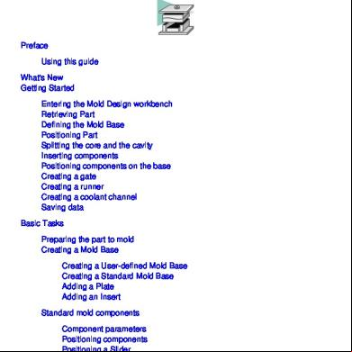
Mold Tooling Design Catia 4gn4
December 2019 76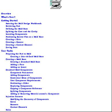
Catia Mold 5o3g2
August 2020 0
Catia V5 - Mold Tooling Design Course 391q5d
December 2019 70
Catia V5r17 Coil Spring Simulation 183o3u
April 2020 25