780_09914 Zprinter 650 Installation Manual Rev B[1].pdf 1k3p1j
This document was ed by and they confirmed that they have the permission to share it. If you are author or own the copyright of this book, please report to us by using this report form. Report 3i3n4
Overview 26281t
& View 780_09914 Zprinter 650 Installation Manual Rev B[1].pdf as PDF for free.
More details 6y5l6z
- Words: 6,465
- Pages: 40
09914
ZPrinter 650 Installation Manual Rev B
Description: This procedure describes how to install a ZPrinter 650 at a customer site. This procedure is intended to be performed by an installer trained to install the ZPrinter 650.
Prerequisites: • • • • •
Installer/trainer must have been trained by Z Corporation in proper installation methods and practices. ZPrinter 650 must be at the customer’s facility. Customer must have any necessary site prep completed. This includes any power, network, partitions or other work. The customer must designate a computer that will be used to run ZPrint software and control the Z650. It is suggested the customer set up a specific work area for using the Z650 – typically this would include a table or two, the computer workstation, and shelves for supplies and printed parts.
Equipment / Parts Required: • • • • • • •
ZPrinter 650 and its accompanying Starter Kit, Accessories Kit, etc. Dealer tool kit Heavy duty wire cutters – to remove the metal straps 9/16” Hex socket – to remove the fasteners on the pallet Scissors – to remove the shrink wrap Phillips screwdriver – for removing s T-Handle Hex Driver (Supplied) – to release the lockout screws on the feeder
Procedure: The high level process is as shown below. More details are provided in the sections that follow. 1 2 3 4 5
Uncrate and Inspect the Printer Move Into Location Unpack and Inspect Accessories and Supplies Inspect Interior of Machine Remove Shipping Restraints
09914 ZPrinter 650 Installation Manual Rev B.docx
1/40
6 7 8 9 10 11 12 13 14 15 16 17 18 19 20 21 22
Lubricate the Slow Axis Connect to Power and Network Load With Fluids Check Fast Axis Alignment Install Carbon Filter Bleed Binder Lines Install Print Heads Prime the Cleaning Solution Line Load Powder Install Software Tune Feeder Output Check the Fill Bed Function Align the Printheads Replace All Covers Setup 650 for First Customer Build Making Electronic Connections with ZCorp. Complete Required Paperwork
Overview
Installation of the Z650 is a two-day process.
Day 1 • • • •
Day 2 • • •
The installer uncrates, inspects, and sets up the printer. The customer observes while the installer explains and operates the machine. The customer checks the printer and starts their first build. The following training points should be covered: o Point out key modules of the 650 to the customer (pictures in Quick Start Guide). o Discuss the Fast Axis Assembly. o Discuss the purpose of the Service Station and Parking Caps. o Identify the Electronics Box and the power switch. o Point out that the vacuum hose may be unplugged and used to clean the build bed. o Demonstrate how to check and clean the printer for a build. o Describe the steps in post-processing; demo the tray, air wand, and filter. o Teach the customer how to use ZPrint, ZEdit and ZEdit Pro. Be sure to ZEdit Pro. o Walk the customer through getting a part into ZPrint and ready to print. o Monitor file and software manipulation o Monitor printer preparation o Help the customer as they print a part and perform the post-processing steps. Explain how to do it and why. o Reinforce the steps in checking and cleaning the printer prior to and after each build. The customer completes their first build, and completes post-processing of their part. The installer observes the customer, being sure to talk the customer through all of their actions. The installer reinforces with the customer the critical importance of proper cleaning and maintenance procedures.
09914 ZPrinter 650 Installation Manual Rev B.docx
2/40
•
•
The following training points should be covered: o Help the customer and explain how and why as they print a part and perform the post-processing steps. o Review customer removing part o Monitor rough and fine de-powdering techniques o Ensure that the part is handled carefully to ensure survivability o Monitor infiltration application methods o Review customer preparing another build o Explain the “Maintenance Screen” feature within the ZPrint service menu o Show how to assemble the grease gun. o Demo the lubrication of the build piston screw using grease gun. o Demo the use of the grease gun on the Slow Axis fitting. o Demo the use of the oil on the Fast Axis fitting.
The installer completes the necessary paperwork to record the installation.
Installer Notes •
•
•
It is important to make the customer feel at ease using the machine. While demonstrating, tell the customer why you do things and why you do them that way. By the end of the installation, the customer should have done everything in the printing process by himself or herself. Keep in mind that the customer has things they need to accomplish during their day. They will need to take breaks at certain points during the training. So be sure to talk with the customer about this and have a plan for lunch and other breaks. Encourage the customer to ask questions. Let them know they can interrupt you at any point. If you don’t know an answer to a question, don’t panic. Let them know you can get the answer with a call back to the office.
09914 ZPrinter 650 Installation Manual Rev B.docx
3/40
1 Uncrate and Inspect the Printer 1.1 Uncrate The ZPrinter 650 is shipped on a wooden pallet with a cardboard cover. Uncrating consists of removing the cover and rolling the machine off the pallet. 1. Position the crate where there is room to attach the ramps and roll out the machine.
CHECK DIAGRAM – dimensions are guesses 87”
61”
82” minimum
2. Remove the shipping straps and lift off the top cardboard cover. 3. Pull out the foam blocks at the four corners and front of machine. 4. Detach the removable side of the wooden frame (9/16 socket). Crate Ramp 5. Detach the ramps and position as shown (9/16 socket). Z650 6. Cut the large zip-ties that attach the machine to the pallet. 7. Carefully roll the machine downRamp the ramps.
1.
2.
Open the flap on the end of the box and remove the Power Cord and any shipping documents.
Cut the metal strapping and lift off the top cover of the crate.
09914 ZPrinter 650 Installation Manual Rev B.docx
4/40
3.
Remove the 8 clamps that tie the corners of the crate together. A flat blade screw driver may be useful for lifting the clamp. 5.
Remove the three foam pads from the front of the printer.
4.
Lift away all four sides of the crate and remove the two foam blocks that protect the rear of the printer.
6.
Remove the end brackets at both ends of the printer by pulling up evenly.
7.
8.
Using a 9/16” socket or wrench, remove the ramps from either side of the pallet.
Attach the ramps to the end of the pallet as shown.
09914 ZPrinter 650 Installation Manual Rev B.docx
5/40
9.
10.
Locate the two hold-down brackets under the printer.
Unbolt the hold-downs and unhook them from the eye bolts on the printer.
11.
12.
Carefully roll the printer down the ramps. It is recommended to use two people, one in front of the printer to slow its descent and another to steer the wheels down the ramps.
Remove all shrink wrap and bubble wrap from the printer.
1.2 Inspect Exterior of Machine Visually inspect the exterior of the machine for any damage incurred during shipping. Notify Z Corporation Service immediately if anything is evident at this point. DO NOT proceed with the installation until you have discussed the damage with Service.
2 Move Into Location
Work with the customer to determine the best location for the machine, considering such factors as ease of access and proximity to the necessary connections.
09914 ZPrinter 650 Installation Manual Rev B.docx
6/40
2.1 Check Access Before moving the printer, check the access to the work location. Any corners, doorways, etc. must be large enough to maneuver the printer through.
Z650
6’ min. 6’ min.
If the access is too restricted to allow the printer to through, the Post-Processing Unit (PPU) will have to be separated from the printer so the printer and PPU can be moved separately. When they are in their final location, they can be re-attached. The separation and attachment are simple procedures, taking only a few minutes. The procedures are described in Appendix 1 – Separating and Attaching the PPU.
2.2 Moving the Printer Roll the machine to its final location. Roll along carefully. Go slowly over bumps such as floor expansion ts. Get help when going down or up ramps.
09914 ZPrinter 650 Installation Manual Rev B.docx
7/40
3 Unpack and Inspect Accessories and Supplies 3.1 Accessories Kit The Accessories are packed in a series of foam trays, inside the Post-Processing Storage compartment. • • • •
Check that all items are present and undamaged. Assemble the plastic tip onto the squeeze bottle. Attach the tip to the air wand. Store the Accessories in the door pockets provided. Suggested locations are shown.
Refer to the photos below.
Tray 1 Tray 2 Tray 3 Tray 4 Part Trays
Tray 1
09914 ZPrinter 650 Installation Manual Rev B.docx
Tray 2
8/40
Tray 3
Plastic tip installed
Tray 4
Wand tip installed Quick Start Guide Small Syringe & Needles Water Bottle Oil Printheads Alcohol Swabs Large Syringe Needle & Tubing Assembly Pick Hex Wrench Printer Door
09914 ZPrinter 650 Installation Manual Rev B.docx
Grease Gun
9/40
Vacuum Attachments - Near Vacuum Hose Brushes - Brush Tray in PPU
Accessory Tray – PPU Door Dipping Kit & Part Trays – PPU
3.2 Starter Kit Unpack the Starter kit. Check that all items are present and undamaged. Place everything neatly in a location convenient to the machine. Contents of Starter Kit Item Packaging ZCorp. Part No. Quantity in Kit Zp131 Powder 8 kg cartridge 50307 7 Zb61 Binder
---
---
---
Clear
1 L cartridge
06971
6
Black
1 L cartridge
50333
4
Cyan
300 mL cartridge
50332
6
Magenta
300 mL cartridge
50331
6
Yellow
300 mL cartridge
50330
6
1 L cartridge
50315
6
HP 11 Print Head
each
5
Carbon Filter
each
15254 31593
Waste Tray
each
50065
1
Alcohol Swabs
each
12073
20
Dipping Kit
each
50301
1
Zc6 Cleaning Solution
09914 ZPrinter 650 Installation Manual Rev B.docx
1
10/40
4
Inspect Interior of Machine
Before powering up the machine, remove the covers and make an internal inspection.
4.1 Remove Covers 1. Locate the 9 screws on the back cover on the printer side of the machine. 2. Remove 4 screws each on the right and left edges of the cover. Leave the top center screw in place. 3. Holding the cover against the machine, remove the top center screw.
4. Tilt the cover back towards you. Remove the cover by lifting it out of the two slots.
5. Remove the side cover by pulling straight outward to disengage the spring detents. Pull first at the top, then pull out at the bottom.
09914 ZPrinter 650 Installation Manual Rev B.docx
11/40
6. Remove the top cover by lifting the back edge and sliding the cover toward the rear of the machine. Then lift it off.
4.2 Inspect “Tip and Tell” Check the “tip and tell” indicator, located near the binder reservoirs in the rear of the printer. Blue beads above the indicator line means that the system has been mishandled. Call Z Corporation Service Dept. immediately if blue beads are above the line. DO NOT proceed with the installation until you have discussed this with Service.
4.3 Inspect E-Box Connections Tilt out the Electronics Box (E-Box) and check that all connections are secure. 1. Unscrew the four screws shown from the E-Box.
2. Tilt the E-Box out toward you.
09914 ZPrinter 650 Installation Manual Rev B.docx
12/40
3. Check all cable connections at the E Box. Make sure they are all seated securely.
4. Replace the E-Box in position and reinstall all 4 screws.
4.4 Inspect Rest of Interior Make a general inspection of the rest of the interior of the machine. Look for any tubing, vacuum lines, connectors, etc. that may have become dislodged during shipping. Leave all the covers off until the installation process is complete.
5 Remove Shipping Restraints 5.1 Unlock the Feeder The Feeder is secured against movement and damage during shipping by four lockout screws. These screws hold the feeder up off the load cell that monitors its weight. Releasing the feeder consists of screwing these lockouts in, thus lowering the feeder onto the load cell. 1. Locate the screws, two on each side of the Feeder. 2. Using the 5/32” T-handle wrench (located inside the rear cover of the printer), turn each lockout screw clockwise as far as it will go.
09914 ZPrinter 650 Installation Manual Rev B.docx
13/40
5.2 Free the Fast Axis To free the Fast Axis, carefully remove the cardboard and foam shipping restraints. First lift out the section in the Build Bed, then slide the Fast Axis toward you and slide the restraints out from under the Fast Axis. the Fast Axis as you do this.
09914 ZPrinter 650 Installation Manual Rev B.docx
14/40
6 Lubricate the Slow Axis Before the printer is run, perform the lubrication as described below.
NOTE: Do NOT lubricate the Fast Axis during installation. It was fully lubricated at the factory. ONLY add oil when ZPrint prompts you to as part of routine maintenance. Too much oil will damage the printer.
1. Locate the round plastic cover on the Deck to the left of the Build Bed, near the Service Station. 2. Take a flat head screwdriver or a Pick Tool and pop the round cover off. Be careful not to scratch the deck surface. An alternative method is to reach your fingers under the left side of the deck and pop the cover off from underneath. 3. Pull the Fast Axis forward until you see that hole in the center of the opening on the Fast Axis. You should see the Slow Axis bearing grease fitting inside the hole. 4. Assemble the grease gun that is part of your Accessories Kit according to the instructions found in the document 09576 Grease Gun Loading Instructions, which is supplied in the materials that accompany the printer. 5. Squeeze the handle until grease dispenses from the tip. Wipe clean with a clean paper towel. 6. Place the tip of the grease gun over the grease fitting. Squeeze the trigger 2 - 3 times or until you feel the tension change and then STOP. Do not over-grease. 7. Slide the Fast Axis forward and back several times to distribute the grease evenly. 8. Replace the plastic cover.
09914 ZPrinter 650 Installation Manual Rev B.docx
15/40
7
Connect to Power and Network
7.1 Power Note to Installer Most facilities have one breaker for 5 or 6 outlets. It is best to not share the circuit that the ZPrinter 650 is using with other equipment. Sharing the circuit with other equipment might exceed the Wattage of the supplying circuit breaker and cause it to trip. 1. Install Power Cord. 2. Connect power cord to AC Mains outlet.
Power Switch
Power Cord Network Connection
7.2 Connect/Configure Network Turn system on and wait for the Installation menu to appear. Follow the instructions and complete each task before selecting CONTINUE. Notes to Installer • •
•
ALL NETWORK CONNECTIONS MUST BE APPROVED BY THE CUSTOMER OR CUSTOMER’S IT MANAGER PRIOR TO INSTALLATION. If at all possible set up the default connections: o ZPrinter 650 connected to Ethernet network running DH. o Dedicated computer connected to same network.
If the customer wants one of the following configurations, refer to the document 08605 Setting Ethernet Connections To Z Corporation 3D Printers, available on our Website: zcentral.zcorp.com . o Printer connected through a hub or switch with uplink to network. o Printer connected directly to PC (requires crossover cable). o Printer connected directly to PC (requires crossover cable); PC has second network card installed (allows connection to network).
INSTALLATION MODE RJ-45 Ethernet Connector CONTINUE CONNECT PRINTER TO NETWORK WITH ETHERNET CABLE CONTINUE 09914 ZPrinter 650 Installation Manual Rev B.docx
16/40
USE AUTOMATIC (DH) NETWORK SETUP? YES NO
YES (Default) Continue to next step.
NO Please refer to the document “08605 Setting Ethernet Connections to Z Corporation 3D Printers” for static IP address setup instructions. This document is available on our web site: zcentral.zcorp.com.
09914 ZPrinter 650 Installation Manual Rev B.docx
17/40
8 Load With Fluids 8.1 Install Waste Tray The Waste Tray contains absorbent material to soak up ink, binder, and wash fluid. A load cell monitors its weight to detect when the tray is full and needs replacing. NOTE: Always use the correct ZCorp. Waste Tray (part # 50065). Not using the correct Waste Tray can lead to spillage of waste and/or damage to your printer. 1. Locate the Waste Tray in the Accessories Kit. 2. Slide the Tray into its compartment on the printer.
INSERT WASTE TRAY
CONTINUE
8.2 Load 1st Set of Fluids 1. Locate the fluid cartridges in the Startup Kit. 2. Slide each cartridge into its “pocket” on the printer. 3. Wait 5 minutes for the cartridges to drain, then select CONTINUE. INSERT FLUID CARTRIDGES (SET 1) CLEAR, BLACK, CMY AND CLEAN CONTINUE Clear
Black
The system is shipped with the internal fluid reservoirs empty. It takes multiple cartridges to fill each reservoir.
CMY
09914 ZPrinter 650 Installation Manual Rev B.docx
Wash
18/40
8.3 Install Debris Separator INSTALL DEBRIS SEPARATOR FROM ACCESSORIES KIT CONTINUE
8.4 Load 2nd set of fluids 1. Remove all 6 fluid cartridges. 2. Slide a fresh cartridge into each pocket on the printer. 3. Wait 5 minutes for the cartridges to drain, then select CONTINUE.
REMOVE ALL EMPTY CARTRIDGES
CONTINUE Clear
Black
INSERT FLUID CARTRIDGES (SET 2) CLEAR, BLACK, CMY AND CLEAN CONTINUE CMY
09914 ZPrinter 650 Installation Manual Rev B.docx
Clean
19/40
8.5 Load Final Set of Fluids 1. Remove all fluid cartridges EXCEPT the black (5 total). 2. Slide a fresh cartridge into each of the 5 pockets on the printer. 3. Wait 5 minutes for the cartridges to drain, then select CONTINUE. LOADING OF BLACK BINDER IS COMPLETE
Only two cartridges are needed to fill the black reservoir. All other reservoirs will require a third cartridge.
CONTINUE REMOVE EMPTY CLEAR CMY AND CLEAN CARTRIDGES CONTINUE
Do not remove the Black Cartridge
Clear
INSERT FLUID CARTRIDGES (SET 3) CLEAR CMY AND CLEAN CONTINUE
CMY
09914 ZPrinter 650 Installation Manual Rev B.docx
Clean
20/40
8.6 Install Spit Plate and Parking Caps 1. Locate the Spit Plate and Parking Caps. They will be taped to the Build Plate.
2. Install the Spit Plate on the Service Station as shown.
3. Slide the Carriage to the left and install the parking caps on the Parking Spittoon as shown.
INSTALL SPIT PLATE AND PARKING CAPS
CONTINUE
09914 ZPrinter 650 Installation Manual Rev B.docx
21/40
9 Check Fast Axis Alignment Check the Fast Axis module to be sure it is not twisted. A twisted Fast Axis can cause incomplete filling of the build bed (short spreading) and other problems. 1. Pull the Fast Axis out to about the middle of the Build Bed. 2. At each end of the Fast Axis, press down on the front and rear corners as shown by the arrows. The end of the Fast Axis should not rock back and forth. (The bottom of the Fast Axis should the shaft at both ends with no free play.) 3. If free play is detected, grasp the end plate and untwist the fast axis so that it sits flat on the shaft.
10 Install Carbon Filter
1. Unlatch the Post-Processing Tray and lower it to the bottom of the Post-Processing Unit. 2. Press the button to unlatch the Carbon Filter retainer and lower the retainer. 3. Install the Carbon filter with the label at the top and facing out at you. 4. Make sure the two tabs on the retainer are properly seated in their slots below the filter. 5. Lift the retainer into position and latch it closed.
INSTALL CARBON FILTER FROM ACCESSORIES KIT CONTINUE
09914 ZPrinter 650 Installation Manual Rev B.docx
22/40
11 Bleed Binder Lines 1. Open the Print Head Cover on top of the Carriage. 2. Visually locate the 5 Septa (small circular ports). 3. Find the Needle Tubing Assembly that is part of the Accessories Kit. 4. Place the open end of the tubing in the Service Station as shown. 5. Press the Print Head fitting over the first Septum so that the needle in the fitting penetrates the rubber membrane of the Septum. 6. Observe the fluid running through the tubing. Let it drain until no more bubbles are visible (approx. 30 seconds). 7. Remove the needle from the Septum, leaving the end of the tubing in the Service Station. 8. Insert the needle in the next Septum. 9. Repeat the process for all 5 Septa. 10. Close the Carriage Cover.
Septum
These steps are necessary only during installation and are not required as part of future head changes.
INSTALL COMPLETE ADD POWDER AND PRINTHEADS AFTER PRINTER REBOOTS REBOOT PRINTER REBOOTS
09914 ZPrinter 650 Installation Manual Rev B.docx
23/40
12 Install Print Heads 1. On the LCD, select PRINTHEADS, then CHANGE PRINTHEADS.
2. Remove the protective tape, and Install the HP11 Print heads. 3. Check that the Heads are properly seated by pushing gently on the front edge of the head (the edge without the arrow). Close the Head cover and select CONTINUE. DEPOWDER PREP BUILD CHAMBER STATUS REPORT PRINTHEADS
BUILD CHAMBER
MAIN MENU CHANGE PRINTHEADS ALIGN PRINTHEADS PURGE PRINTHEADS
INSERT NEW HEADS AND PRESS CONTINUE CONTINUE CANCEL
13 Prime the Cleaning Solution Line VACUUM DEPOWDER PREP BUILD CHAMBER STATUS REPORT PRINTHEADS
Enable the Service Menu by selecting STATUS REPORT
and holding in the control knob for 5 seconds
SERVICE MENU ENABLED
CONTINUE
09914 ZPrinter 650 Installation Manual Rev B.docx
24/40
PRINTHEADS
BUILD CHAMBER
SERVICE MENU
POST PROCESS MENU GO ONLINE
Select SERVICE MENU
SERVICE HEADS TEST HEADS PRIME CLEAN SOLN CALIBRATE WASTE STRIPE TEST
MAIN MENU UNPARK TOGGLE ROLLER EMPTY FRONT OVERFLOW EMPTY REAR OVERFLOW EMPTY FEEDER
Select PRIME CLEAN SOLN
Wait for the automatic priming sequence to complete. Then scroll up to the top of the service menu and select MAIN MENU
09914 ZPrinter 650 Installation Manual Rev B.docx
25/40
14 Load Powder
We suggest loading 4 cartridges of powder now to allow you to complete the installation process. More powder can be added later when the customer needs to run a large build. NOTES: • • •
The LCD display will not update and show powder levels until after the first 1-2 cartridges are loaded. This is normal. The first cartridge “primes” the feeder and the second starts to supply usable powder. Four cartridges of powder will yield about 5 inches of powder in the feeder. It takes a total of approximately 6.5 cartridges of powder to fill the feeder.
1. Invert and shake the Powder Cartridge before opening to help loosen powder that may have packed down during shipping. 2. Set the Powder Cartridge in the PPU. 3. Remove the gray sealing cap. 4. Insert the hose into the Powder Cartridge. 5. On the LCD, select VACUUM; the vacuum starts.
6. Observe the Debris Separator – if powder is loading into the printer, you will see powder swirling in the Separator. 7. Shake the Cartridge frequently to keep powder flowing. 8. The vacuum will automatically shut off when powder stops flowing into the feeder VACUUM DEPOWDER PREP BUILD CHAMBER STATUS REPORT PRINTHEADS VACUUM STARTING
VACUUM ON AVAILABLE POWDER: 0.0”
Note that you may have to load two complete cartridges before the powder level on the LCD will start reading. This is normal and does not indicate a problem with the Load Cell.
09914 ZPrinter 650 Installation Manual Rev B.docx
26/40
th
9. Repeat the steps above with 3 more new Cartridges. When the 4 Cartridge is empty, select GO ONLINE. Four cartridges of powder will yield about 5 inches of powder in the feeder. NOTE: In day to day operation, make sure that the build bed and overflows are empty before adding powder. Otherwise when this powder is recovered, the system could be overfilled and the vacuum will not work. Always use the STATUS REPORT function to check the actual powder level.
15 Install Software
Install the ZPrint/ZEdit software. Refer to Chapter 1 of the ZPrint Manual. Notes to Installer •
•
The customer MUST have privileges on the computer the where software will be installed on AND the computer must meet or exceed the specifications stated in the ZPrinter 650 Hardware Manual. Don’t forget to disable any screen savers on the desktop computer. Disable all power saving settings. (Some computers ship with a 30 minute time-out on the disc drives. This will stop a print job after 30 minutes.)
ZEdit Pro If the customer has also purchased ZEdit Pro, install that now. Note to Installer Make sure you complete the licensing process to activate this copy of ZEdit Pro. Refer to the installation paperwork that was shipped with the printer, or consult the ZEdit Pro online Manual.
09914 ZPrinter 650 Installation Manual Rev B.docx
27/40
16 Tune Feeder Output
After loading the powder and binder cartridges, run the TUNE FEEDER CONTROL before starting a job. This automatic adjustment will run for about 20 - 30 minutes. During this time the feeder will spread multiple layers of powder while monitoring the output of the feeder’s load cell. It will calculate the weight of the powder that has been spread and fine tune the load cell loop for maximum accuracy of powder feeding. This is required only once during installation (or if installing a new feeder). VACUUM DEPOWDER PREP BUILD CHAMBER STATUS REPORT
Select PREP BUILD CHAMBER
PRINTHEADS
PRINTHEADS
BUILD CHAMBER
The Build Bed rises into position.
Select SERVICE MENU
POST PROCESS MENU GO ONLINE SERVICE MENU REZERO SERVOS REZERO PISTON REZERO AIRVALVE REZERO FILTER TUNE FEEDER CONTROL
Select TUNE FEEDER CONTROL
TUNE FEEDER CONTROL FEEDER CAL VALUES WASTE CAL VALUES NETWORK SETTINGS REBOOT
Wait for the Tune Feeder routine to complete, then select REBOOT Note to installer: Be sure to reboot the printer to hide the Service Menu. This will prevent any potential problems from the customer accessing Service functions.
09914 ZPrinter 650 Installation Manual Rev B.docx
28/40
17 Check the Fill Bed Function
Check that the automated FILL BED function is executing enough spreads to completely fill the Build Bed. If not, edit the [.ini] file to ensure the bed completely fills. 1. Vacuum out all powder from the Build Bed. 2. On the LCD, select PREP BUILD CHAMBER.
3. On the LCD, select BUILD CHAMBER, then FILL BED.
4. Watch the printer and note if it completely fills the bed.
Example of good Fill Bed • •
FILL_BED_SPREADS set too low
If the Bed is completely filled, vacuum the build bed. You are ready to help the customer start their first build. If the Bed is NOT completely filled, you will need to edit the printer’s .ini file. o In the ZPrint menu bar, select Service then Edit .INI file. o In the .ini file, set the variable “FILL_BED_SPREADS” to a higher number. We recommend increasing it by 5. The range of input for this variable is 15 to 30. o Click SAVE AS to save the .ini file. Use the original file name. o The printer will automatically reboot after the change to the .ini file.
09914 ZPrinter 650 Installation Manual Rev B.docx
29/40
When the reboot is complete, repeat the steps above beginning with Step 1 (vacuum the Bed). Again note if the bed fills completely. • •
If it does, you are done; help the customer set up for their first build. If it does not, repeat editing the .ini file and use a higher number. Then repeat these steps until the Bed fills completely.
If using a value of 30 does not fill the bed, there may be something wrong with the Feeder. ZCorp. Service to resolve the problem.
18 Align the Printheads
As the final step in the installation, align the print heads for best accuracy. 1. Vacuum out all powder from the Build Bed. 2. On the LCD, select PREP BUILD CHAMBER.
3. On the LCD, select FILL BED.
4. On the LCD, select PRINTHEADS.
5. On the LCD, select ALIGN PRINTHEADS.
The printer now prints and scans an alignment pattern. The printer will automatically adjust its printing parameters to optimize accuracy.
09914 ZPrinter 650 Installation Manual Rev B.docx
30/40
19 Replace All Covers 1. Replace the top cover by sliding its front edge into position and then lowering the back edge into position. Make sure the screw holes line up.
2. Replace the side cover by aligning the pegs with the spring detent holes, then pushing straight in until the pegs snap into place.
Note: Replacing the screws in the following steps is easiest if you install each screw a few turns, and then tighten them after all screws are in place.
3. Engage the lower edge of the rear cover with the slots on the machine. Tilt the cover up into position.
4. Hold the rear cover against the machine so the screw holes in the top and rear covers are properly aligned. 5. Replace the top center screw. 6. Replace the other two screws along the top edge of the cover, again aligning the screw holes in the top and rear covers. 7. Replace the remaining 3 screws on each end of the rear cover. 8. Tighten all screws securely.
09914 ZPrinter 650 Installation Manual Rev B.docx
31/40
20 Setup 650 for First Customer Build Review and demonstrate the printer menus • •
Go through menu structures on the system LCD . Show the customer the “Status Report” screens on the LCD and explain what each line means.
Review and demonstrate ZPrint • • • • • •
Set-up the color blocks build in ZPrint. Click on 3D Setup and walk the customer through the options. Click on 3D Print and explain the functions of the status dialog box. Start the print job. Demonstrate the real-time update of the status dialog. Point out that the LCD system display shows up in ZPrint. Explain the pre-build routine (fill bed, purge print heads, print head alignment, spread layer, and print job).
Discuss post build steps • •
Demo the gross and fine de-powdering techniques for powder removal. Demo the infiltration of the part.
Prep the 650 for the next build • • •
Discuss importance of the cleanliness techniques. Demo cleaning the Service Station and Parking Caps. Demo overall machine cleaning tips.
Teach the ZPrint and ZEdit Software • •
Discuss in detail all ZPrint and ZEdit Software menu features and options. Highlight all features that may pertain to the customer’s specific applications.
If possible, have the customer set up a build to run overnight. Note to installer: Review the Overview Section on page 2 and be sure you’ve covered all the training topics. Doing a good job now will save time and service calls later!
09914 ZPrinter 650 Installation Manual Rev B.docx
32/40
21 Making Electronic Connections with ZCorp. Familiarize the with the web site (zcentral.zcorp.com). At a minimum make sure they know: • Where to Firmware and Software • Where the MSDSs are located • How to order consumables through Z Shop • Where to find the Training Modules • How to for the Message Board Introduce the customer to [email protected] for any non-service related technical .
22 Complete Required Paperwork Complete and Return the required Service Installation forms to the Z Corporation Service Department for customer tracking purposes: • •
Customer Acceptance & Training Form (#09953) Installation Review Form (#09954)
09914 ZPrinter 650 Installation Manual Rev B.docx
33/40
Appendix 1 – Separating and Attaching the PPU
The steps below are taken from ZCorp. Procedure # 85033 PPU Separation Attachment. The steps are reproduced here for the convenience of the installer. For the latest updates on this procedure, check our website: zcentral.zcorp.com.
Procedure: SEPARATION
Turn the system power switch OFF and unplug the power cord from the system. Remove the 12 Phillips screws from Post Processing Unit (PPU) rear cover. Set cover aside.
A large hex wrench is clipped inside the rear of the PPU. This will be used for removing the bolts that attach the PPU to the Printer Unit.
09914 ZPrinter 650 Installation Manual Rev B.docx
34/40
Remove the connectors from the bottom of the . Note- Molex connectors have locks that must be depressed before pulling the connector out.
Loosen the hose clamp and remove vacuum hose. Move the hose over to the base of the main system for safe keeping.
Reaching in from the rear of the PPU, remove the two shoulder screws (one toward top and the other toward bottom). Save the screws.
09914 ZPrinter 650 Installation Manual Rev B.docx
35/40
Open the door at the front of the PPU and find the access hole. Remove the shoulder screw and save the screw.
Pull the PPU away from the system. Notice the alignment pin that is used to re-attach the PPU.
09914 ZPrinter 650 Installation Manual Rev B.docx
36/40
ATTACHMENT
To attach the PPU to the system, first push the PPU toward the system until the alignment pin (shown in previous step) mates with the hole. Make sure the PPU is pushed tightly against the system and insert one of the shoulder screws. It is a good idea to get all screws started before tightening the screws.
Re-attach the vacuum hose and tighten the clamp. Re-attach the two Molex connectors.
09914 ZPrinter 650 Installation Manual Rev B.docx
37/40
Make sure the vacuum hose and wiring are secure and install the rear PPU (12 screws). Plug in the power cord and switch the system on.
09914 ZPrinter 650 Installation Manual Rev B.docx
38/40
Change History
Rev A ECN 2574 RAB/BWH 10/22/2008 Rev B ECN 2647 RAB/BWH 1/12/2009
Notices Copyright and Trademarks Copyright © Z Corporation 1995-2009. All rights reserved. The information in this document may not be duplicated or transmitted in any way without the express written consent of Z Corporation. The information contained herein is for the use of Z Corporation customers, who are permitted to create brief excerpts for the purposes of training and review. This information may not be incorporated in any commercial programs, books, databases, or in any kind of software without the consent of Z Corporation. Z, Z Corporation, zp, zb, ZMap, ZPhoto, Z-Cure, Z Prints, ZPrinter, ZCast, ZScanner, ZScan and the Z Corp. logo and design are pending/ed trademarks of Z Corporation. ZPrint® 7.8 System Software Copyright (c) 1996-2009 Z Corporation. This software is based in part on the work of the Independent JPEG Group. PNG library libpng version 1.2.2 Copyright (c) 1998-2002 Glenn Randers-Pehrson, (Version 0.96 Copyright (c) 1996, 1997 Andreas Dilger), (Version 0.88 Copyright (c) 1995, 1996 Guy Eric Schalnat, Group 42, Inc.) ZLIB general purpose compression library version 1.1.4, Copyright (C) 1995-2002 Jean-loup Gailly and Mark Adler. Microsoft Windows is a trademark of Microsoft Corporation. Z Corporation acknowledges the trademarks of other organizations for their respective products or services mentioned in this documentation. Proprietary Information Information contained in this document is the confidential property of Z Corporation. Recipient shall not disclose such Information to any third party, and shall not use it for any purpose whatsoever other than what is required to install and use the ZPrinter 650. Use of Equipment Z Corporation's Equipment, and use of the Equipment, may be subject to limitations imposed under patents licensed to or owned by Z Corp., and is to be used solely for the fabrication of appearance models and prototypes using new Z Corporation-supplied consumables from Z Corporation or its authorized distributors in the original packaging. Other uses may be restricted; Z Corporation for further information. Consult the 's Manual before operation of any Z Corporation Equipment. The Equipment may be covered by the following U.S. Patents and/or U.S. Patent Applications: 5,204,055 5,340,656 5,387,380 6,007,318 6,375,874 5,902,441 6,416,850 6,610,429 6,403,002 5,660,621 5,851,465 6,397,922 6,036,777 6,989,115 7,037,382 7,291,002 7,387,359 7,087,109 7,332,537 11/335,282 11/860,087 60/558,940 12/118,899 11/000,100 11/606,960 60/808,721 11/807,325 11/807,329 11/807,175 11/807,237 09/706,350 09/835,292 11/453,695 60/472,221 60/499,220 11/732,490 60/879,703 11/952,727 12/035,743.
09914 ZPrinter 650 Installation Manual Rev B.docx
39/40
The Equipment is designed to be used by design engineers and other professionals in the production of early-stage 3D appearance models and prototypes. The Equipment is not to be used to produce, either directly or indirectly, medical or other products that may require precise dimensions or tolerances to ensure the safe and effective operation of such products. You agree to indemnify, defend and hold Z Corporation and its officers, directors and employees harmless from and against any and all claims, losses, damages, costs and expenses resulting from any use of the Equipment other than for the production of early-stage appearance models and prototypes. Warranty Your ZPrinter is guaranteed to be free of defects in materials and workmanship, when used for production of early-stage appearance models and prototypes and with Z Corporation consumables, for the period described below under WARRANTY PERIOD. All consumables and materials are guaranteed to perform as described in their specifications when stored and used as directed, up to the expiry date printed on the label. THE COMPANY MAKES NO WARRANTIES, EXPRESS OR IMPLIED, AND DISCLAIMS ALL WARRANTIES INCLUDING, BUT NOT LIMITED TO, IMPLIED WARRANTIES OF MERCHANTABILITY AND FITNESS FOR A PARTICULAR PURPOSE AND ANY OTHER OBLIGATIONS OR LIABILITIES WHETHER IN CONTRACT, WARRANTY, NEGLIGENCE OR OTHERWISE. THE COMPANY IS NOT LIABLE FOR ANY DIRECT, INDIRECT, SPECIAL, PUNITIVE, CONSEQUENTIAL OR INCIDENTAL DAMAGES INCLUDING, WITHOUT LIMITATION, DAMAGES FOR LOSS OF BUSINESS PROFITS OR BUSINESS INTERRUPTION ARISING OUT OF THE USE OR INABILITY TO USE PRODUCTS OR SERVICES SOLD HEREUNDER. IN NO EVENT WILL THE COMPANY'S LIABILITY EXCEED THE TOTAL CHARGE OF THIS Z ZPRINTER 650. WARRANTY PERIOD: In the U.S., warranty is for 90 days and covers service, parts and training material. In the EU, warranty is for 1 year and covers service, parts and training material. Symbols The following symbols are used on the ZPrinter 650 and in this manual. General Caution: should use care to avoid possible damage to equipment. Hot Surface: should use care when working near or on the labeled item. High Voltage: should use appropriate electrical safety precautions.
09914 ZPrinter 650 Installation Manual Rev B.docx
40/40
Related Documents 3h463d
780_09914 Zprinter 650 Installation Manual Rev B[1].pdf 1k3p1j
October 2021 0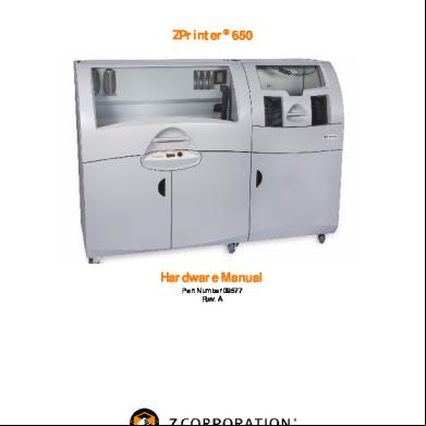
Manual Zprinter 650 - Hardware Overview 2k164q
December 2022 0
Installation Guide Rev.1.0 oke
December 2019 83
November 2019 24

Tangent Hub Installation Manual Rev 21 m61
January 2022 0
Simplex-4004+installation++operating+manual+rev+c.pdf 6v3l24
December 2019 40More Documents from "Michael Piaca Gonzales" 1q1a1w
Kx-ns500 66u1v
October 2019 48
780_09914 Zprinter 650 Installation Manual Rev B[1].pdf 1k3p1j
October 2021 0
4p345f
December 2019 433
Linea De Tiempo Promocion De La Salud 6f57m
May 2022 0
Ejercicios Sobre El Cuadro De Boecio 6l6g4d
November 2019 51